Attenuating filter for ultraviolet light

a technology of ultraviolet light and filter, applied in the field of attenuating filters, can solve the problems of inability to meet the requirements of the requirement directly, platinum exhibits intolerably high degradation, and the deviations are often not directly achieved, and achieves the effect of simple and inexpensive fabrication

Inactive Publication Date: 2007-03-27
CARL ZEISS SMT GMBH
View PDF25 Cites 30 Cited by
  • Summary
  • Abstract
  • Description
  • Claims
  • Application Information

AI Technical Summary

Benefits of technology

[0009]One object of the invention is to provide an attenuating filter for ultraviolet light with wavelengths shorter than 200 nm that is capable of withstanding continuous-duty laser irradiation. It is another object that the attenuating filter should be both simple and inexpensive to fabricate and capable of being antireflection coated, if necessary.
[0013]the filter coating including at least one layer fabricated from a dielectric material that absorbs over a predefined wavelength range. This allows a variation of the transmittance of the filter coating to be obtained by varying the thickness of the dielectric layer.
[0015]An attenuating filter in the sense of the invention that is of that type mentioned at the outset hereof is characterized in that its filter coating consists of at least one layer of a dielectric material that absorbs over that predefined wavelength range to be involved, whereby a major share of its filtering effect will be due to absorption of radiation within the filter coating. The absorbing dielectric material is to be chosen such that it has an effective cross-section at the prescribed operating wavelength that is large enough to ensure that a rapid variation in the transmittance of the layer of dielectric material may be obtained by varying its thickness, if desired. On the other hand, any reductions in its transmittance due to reflection losses will be either low or negligible, which will be particularly highly beneficial in the case of applications that require avoiding stray light and / or employment of filters with high total transmittances. A uniform attenuating effect over the entire filter surface may be obtained if a uniform thickness of the filter coating is applied.
[0018]Employment of tantalum oxide or tantalum pentoxide for fabricating optical filters, particularly interference filters, is, as such, known. However, tantalum oxide, whether alone or admixed with other materials, has thus far largely been employed for fabricating antireflection coatings for the visible spectral region (cf., e.g., German Pat. Nos. DE 690 21 420 C2 or DE 30 09 533 C2). Tantalum oxide is also frequently employed for fabricating coatings that have high transmittances in the visible and high reflectances in the infrared (cf., e.g., German Pat. Nos. DE 38 25 671 and DE 692 08 712). However, in such applications, the absorption of tantalum oxide is negligible.
[0020]Filter coatings with low thicknesses of, e.g., around 1 nm to 2 nm, have another advantage in that they may be effectively antireflection coated employing simply configured antireflection coatings. In particular, uniform antireflection coatings, i.e., antireflection coatings that have virtually constant, low, reflectances over the entire coated surfaces of filters to which they are applied, may be realized employing antireflection coatings with largely uniform thicknesses, since localized thickness gradients in the absorbing coatings involved will usually be so slight that they will have negligible effects on the local angles of incidence on the coated surfaces. The angles of incidence will thus roughly equal the angles of incidence on the substrates involved, which will usually be less than 20°. The angles of incidence on the coated surfaces and the substrates will thus be largely identical, even if the materials from which the respective filter coatings involved are fabricated have relatively low absorption coefficients, k. Effective antireflection coating thus need not be either broadband or effective over widely varying angles of incidence. The preferred, thin, filter coatings, may thus be effectively antireflection coated employing relatively simply configured antireflection coatings.
[0022]Several embodiments of the invention foresee application of an antireflection coating to that face of the substrate of the attenuating filter opposite that to which the filter coating is applied, where the antireflection coating may be either a single-layer or a multilayer coating. The resultant virtual elimination of reflection losses at both the entrance and exit faces of the attenuating filter will allow achieving the best possible (total) reductions of reflection losses, which will be of particular importance in the case of those attenuating filters for controlling illumination levels in the image planes of projection lenses mentioned at the outset hereof, since high illumination levels will allow achieving high wafer through puts and thus cost-effective fabrication of semi-conductor devices.

Problems solved by technology

However, the specified departures are frequently not directly attained in the case of given illumination systems and given projection lenses.
Compliance with this requirement will become increasingly difficult as the wavelengths involved become shorter and the irradiation intensities involved increase.
However, platinum exhibits intolerably high degradation at, e.g., wavelengths of 193 nm and shorter wavelengths.
However, aluminum films are unsuitable for long-term use, since they oxidize within a few minutes.
However, one disadvantage of that approach is that the spectral transmittance of such filters is extremely sensitive to even the slightest variations in the properties of their multilayer stacks due to the steep gradient in their spectral transmittance in the vicinity of their “cut-on” wavelength.
For example, localized de-tuning of their multilayer stacks, such as drifting of their “cut-on” wavelength due to temperature variations, absorption of water by their dielectric films, or accumulations of contamination thereon, may occur after certain periods of irradiation, causing a beam profile to become burned into them, making them unsuitable for further use as spatially homogeneous attenuating filters.
Multilayer dielectric filters of the type whose filtering effects are adjusted by tilting them are unsuitable for use as transmission filters to be installed in the vicinities of the reticle planes of projection illumination systems.

Method used


Image

  • Attenuating filter for ultraviolet light
  • Attenuating filter for ultraviolet light
  • Attenuating filter for ultraviolet light

Examples


Embodiment Construction

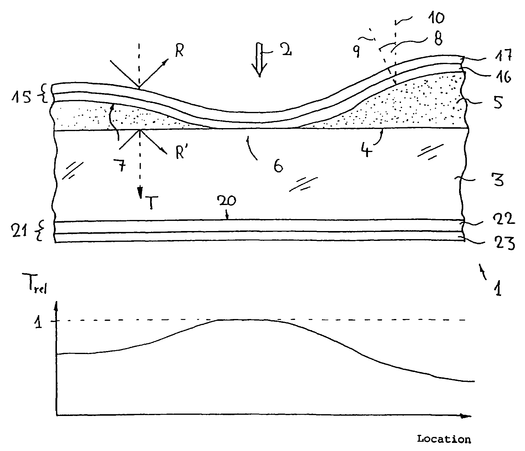
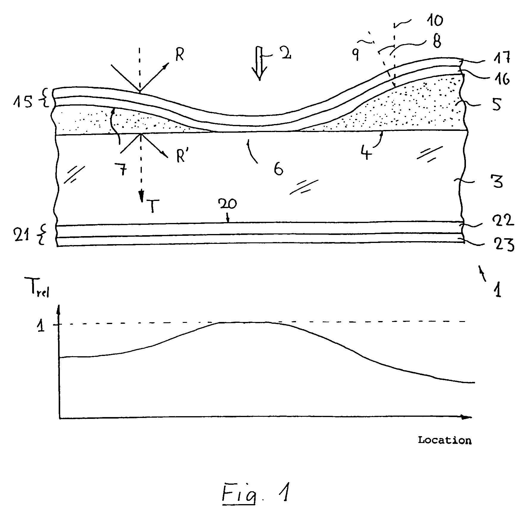
[0029]The upper illustration of FIG. 1 depicts a schematized vertical section through a sample embodiment of an attenuating filter 1 according to the invention. The attenuating filter yields prescribed attenuations of ultraviolet light 2 conforming to a predefinable spatial distribution of the former's transmittance and has been designed for use at an operating wavelength of 193 nm. The attenuating filter has a substrate 3 in the form of a thin, plane-parallel plate fabricated from a material, e.g., crystalline calcium fluoride or quartz, that has virtually no absorption at the operating wavelength. Evaporated onto the planar entrance face 4 of the substrate is an absorbing filter coating 5 in the form of a gradient-filter coating whose local thickness varies continuously over the entrance face, where the thickness of the coating may drop to zero, thereby yielding, as in the case of the example depicted here, zones 6 that are not covered by the coating. The spatial distribution of t...


PUM

PropertyMeasurementUnit
thicknessaaaaaaaaaa
thicknessaaaaaaaaaa
wavelengthsaaaaaaaaaa

Abstract

An attenuating filter provides a prescribed attenuation of the intensity of transmitted, short-wavelength, ultraviolet light, in particular, at wavelengths below 200 nm, that is governed by a predefinable spatial distribution of its spectral transmittance. The filter has a transparent substrate (3), e.g. fabricated from crystalline calcium fluoride. A filter coating (5) fabricated from a dielectric material that absorbs over a predefined wavelength range is applied to at least one surface (4) of the substrate. In the case of operating wavelengths of about 193 nm, the filter coating consists largely of tantalum pentoxide. Filters of the type, which may be inexpensively fabricated with high yields, are noted for their high abilities to withstand laser radiation and may be effectively antireflection coated employing simply designed antireflection coatings.

Description

[0001]This is a continuation of parent application Ser. No. 10 / 151,892 filed on May 22, 2002 now abandoned, and incorporated herein by reference in its entirety. This application is also based on German Patent Application No. DE 101 27 225.1 filed on May 22, 2001, to which priority is claimed and which is incorporated herein by reference in its entirety.BACKGROUND OF THE INVENTION[0002]1. Field of the Invention[0003]The invention relates to an attenuating filter providing a prescribed attenuation of the intensity of transmitted ultraviolet light over a predefined wavelength range according to a predefinable spatial distribution of its spectral transmittance.[0004]2. Description of the Related Art[0005]Attenuating filters of the type usually have a plane-parallel substrate fabricated from a material that has a sufficiently high transmittance for ultraviolet light over the wavelength range to be involved, as well as at least one filter coating that provides the desired spatial distrib...

Claims


Application Information

Patent Timeline
Patent Type & Authority Patents(United States)
IPC IPC(8): F21V9/06G02B5/20C03C17/34G02B5/22G02B1/11
CPCG02B5/208G02B5/20
Inventor WEIGL, BERNHARDPAUL, HANS-JOCHENEVA, ERIC
Owner CARL ZEISS SMT GMBH
Why Eureka
Try Eureka