Complex optical element and method for manufacturing thereof

a technology of optical elements and composites, applied in the field of composite optical elements, can solve the problems of inferior environmental factor resistance, large linear expansion coefficient of plastic lens parts, and large size and weight of optical systems, and achieve the effects of improving environmental resistance, manufacturing at a low cost, and increasing size and weigh

Inactive Publication Date: 2007-03-27
FUJINON SANO
View PDF7 Cites 2 Cited by
  • Summary
  • Abstract
  • Description
  • Claims
  • Application Information

AI Technical Summary

Benefits of technology

[0007]Accordingly, it is an object of the present invention to provide a lens-laminated composite optical element having a plastic lens portion laminated on a plane surface of a vitreous optical element, more particularly, a lens-laminated composite optical element which is satisfactory in environmental resistance and yet which can be manufactured at a low cost, solving the problems of increased size and weight which have thus far been experienced in assembling optical systems incorporating a lens-laminated composite optical element.
[0013]Thus, a small and compact lens-laminated composite optical element is obtained by laminating a filmy plastic lens portion on a plane surface of a vitreous optical element in the manner just described above. The plastic lens portion suffices to have a lens surface of a specified curvature, so that it can be substantially in a thin and filmy form and extremely small in weight. Since the laminated plastic lens portion is in a thin filmy form and strongly bonded on a plane surface of a vitreous optical element, the coefficient of linear expansion of the laminated lens portion is substantially substituted by that of the vitreous optical element. That is to say, the laminated plastic lens portion becomes to have excellent environmental resistance, suppressing fluctuations in curvature of the lens surface under varying temperature and moisture conditions.
[0014]Thus, the lens-laminated composite optical element according to the present invention is composed of a vitreous optical element and a transparent plastic lens which is laminated in a thin filmy form on a plane surface of the vitreous optical element by the use of a molding means. The composite optical element, with complex and composite optical functions, can be assembled into various optical systems in a compact form.

Problems solved by technology

However, in such a case, since individual optical elements are large in thickness, the optical system inevitably becomes large in size and weight.
However, integral molding of a plastic lens has problems in that a plastic lens portion is large in linear expansion coefficient and inferior in resistance to environmental factors such as temperature and humidity.
Alternatively, it is conceivable to add lens functions by injection molding a glass lens on a prism although glass injection molding is very costly and difficult to adopt.

Method used


Image

  • Complex optical element and method for manufacturing thereof
  • Complex optical element and method for manufacturing thereof
  • Complex optical element and method for manufacturing thereof

Examples


Embodiment Construction

[0023]Hereafter, with reference to the accompanying drawings, the present invention is described more particularly by way of its preferred embodiments.

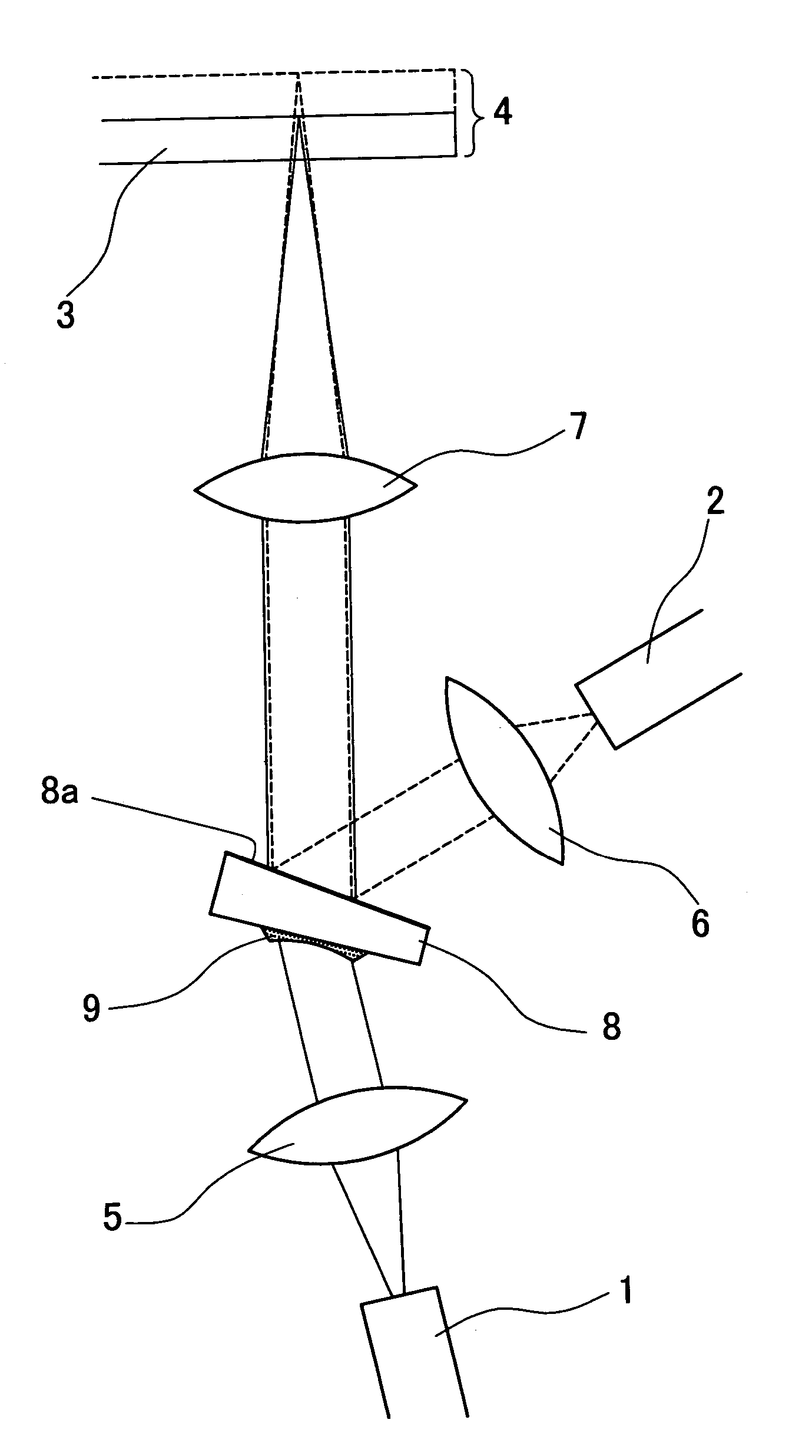
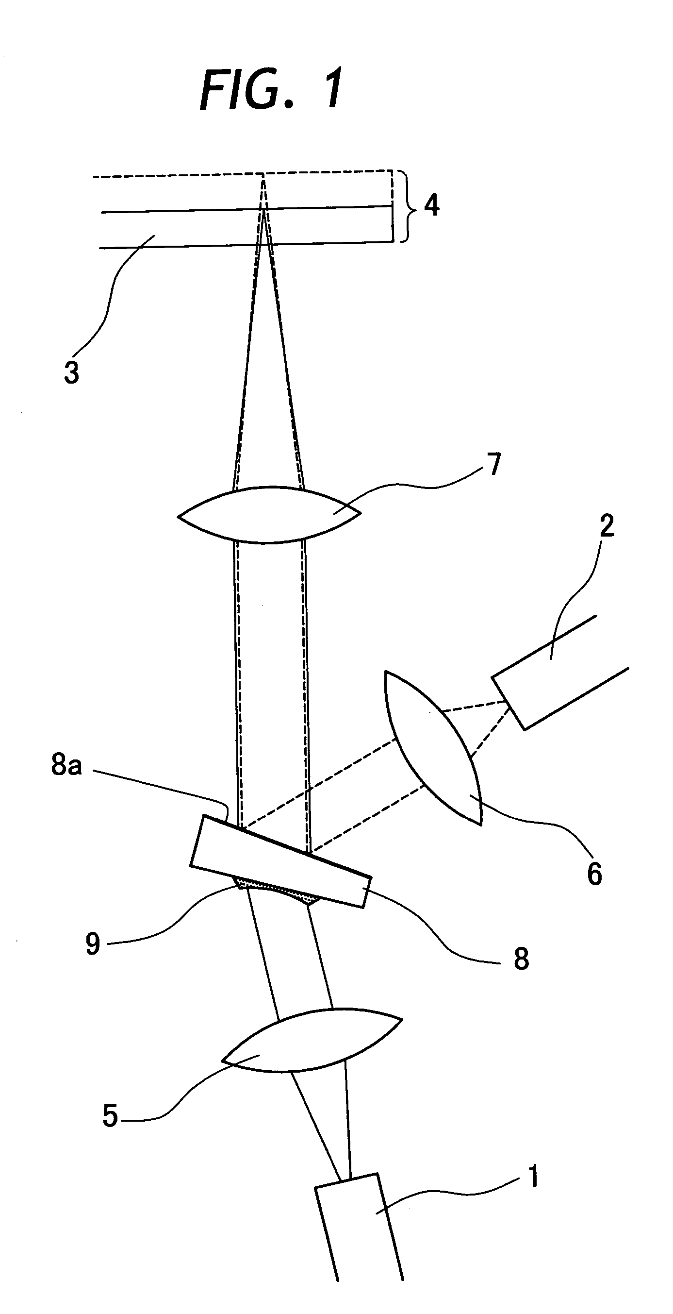
[0024]Referring to FIG. 1, there is shown a first embodiment of the present invention. In this first embodiment, a lens-laminated composite optical element is applied to an optical system of an optical disc pickup as schematically shown in FIG. 1. In FIG. 1, indicated at 1 is a first laser light source, and at 2 a second laser light source. A laser beam of 780 nm wavelength is projected from the first laser light source 1 to read information on a CD 3, while a laser beam of 650 nm wavelength is projected from the second laser light source 2 to read and write information on a DVD 4. The laser beams from the first and second laser light sources 1 and 2 are collimated through collimator lenses 5 and 6 and collimated light fluxes are converged toward CD 3 and DVD 4, respectively.

[0025]Indicated at 8 in FIG. 1 is a polarized prism, and, by...


PUM

PropertyMeasurementUnit
thicknessaaaaaaaaaa
thicknessaaaaaaaaaa
thicknessaaaaaaaaaa

Abstract

A lens-laminated composite optical element composed of a vitreous optical element having a plane surface to perform inherent optical functions, and a thin and filmy transparent plastic lens portion molded in a curved lens profile and laminated on the plane surface of the vitreous optical element by the use of a mold.

Description

BACKGROUND OF THE INVENTION[0001]1. Field of the Art[0002]This invention relates to a complex or composite optical element which basically has inherent optical functions as a prism, half mirror or reflector mirror, and more particularly to a lens-laminated composite optical element having a curved lens portion laminated on a plane surface of a vitreous optical element, either on a plane of incidence or a plane of emergence of light entrance of the vitreous optical element to provide complex or composite optical functions in an optical system.[0003]2. Prior Art[0004]Optical pickup devices are widely in use for reading and writing information on optical discs or similar information recording media. In this connection, currently both CD (compact disc) and DVD (digital versatile disc) are in use as information recording or storage media, and attempts have been made to develop and put in use a CD / DVD drive which is capable of reading CDs and writing and reading DVDs, for example, as desc...

Claims


Application Information

Patent Timeline
Patent Type & Authority Patents(United States)
IPC IPC(8): G02B3/08G02B5/04B29C43/18B29L11/00G02B3/00G02B3/04G02B27/00G02B27/09G02B27/10
CPCB29C43/021G02B3/00G02B3/04G02B5/04G02B19/0028G02B27/095G02B27/1073G02B27/126G02B27/144G02B19/0052G02B27/0031B29C2043/3615B29L2011/0016
Inventor KOMIYA, KEIJIHIROSE, HATSUOYOKOYAMA, IWAOKURAHASHI, HAJIME
Owner FUJINON SANO
Why Eureka
Try Eureka