System and method for optimally configuring border gateway selection for transit traffic flows in a computer network
Active Publication Date: 2007-03-27
ALCATEL-LUCENT USA INC +1
View PDF2 Cites 38 Cited by
Summary
Abstract
Description
Claims
Application Information
AI Technical Summary
This helps you quickly interpret patents by identifying the three key elements:
Problems solved by technology
Method used
Benefits of technology
Benefits of technology
[0007]To address the above-discussed deficiencies of the prior art, the present invention provides a system for, and method of, configuring border gateway selection for transit traffic flows in a computer network. In one embodiment, the system includes: (1) a model of the computer network that includes border routers and their capacities, and distances between the border routers and (2) a traffic flow optimizer, associated with the model. Given input data for transit traffic to the computer network, the traffic flow optimizer uses approximation techniques for integer programs and novel algorithms to improve (and advantageously maximize) resource usage and decrease (and advantageously minimize) cost in the computer network represented by the model.
[0009]In one embodiment of the present invention, the traffic flow optimizer assumes a single egress point for all traffic intended for a given address. Given this assumption, the optimization problem becomes an instance of what is known to those skilled in the pertinent art as the generalized assignment problem (GAP). The approximation algorithm may violate the capacity constraints of the border routers, so in a second phase, the traffic flow optimizer moves traffic from violated routers to routers with spare capacity. Traffic is moved so as to minimize the cost.
[0010]In one embodiment of the present invention, the traffic flow optimizer assumes multiple egress points can be used for traffic to a given address. However, these multiple egress points should respect the proximity constraints of the BGP. The traffic flow optimizer formulates this problem as an integer program then solves the linear program relaxation of the integer program. Approximation techniques are then used to round the linear program solution to an integer solution. The integer solution may violate proximity and capacity constraints, so, in a final phase, the traffic flow optimizer moves traffic from violated routers to routers with spare capacity. Again, traffic is moved so as to minimize the cost.
Problems solved by technology
A poorly designed selection of border routers for the flows of traffic through the ISP can result in numerous problems.
Ingress and / or egress traffic from / to neighbors may exceed the capacity of the selected border routers and its links, causing the ISP to fail to meet its responsibility.
On the other side, underutilization of the potential capacity at border routers, or carrying traffic across the ISP network longer than necessary results in inefficient use of costly resources of the ISP.
Unfortunately, ISPs today have few tools or algorithms to help with this problem.
Method used
Image
Click on the blue label to locate the original text in one second.
Reading with bidirectional positioning of images and text.
Examples
example 1
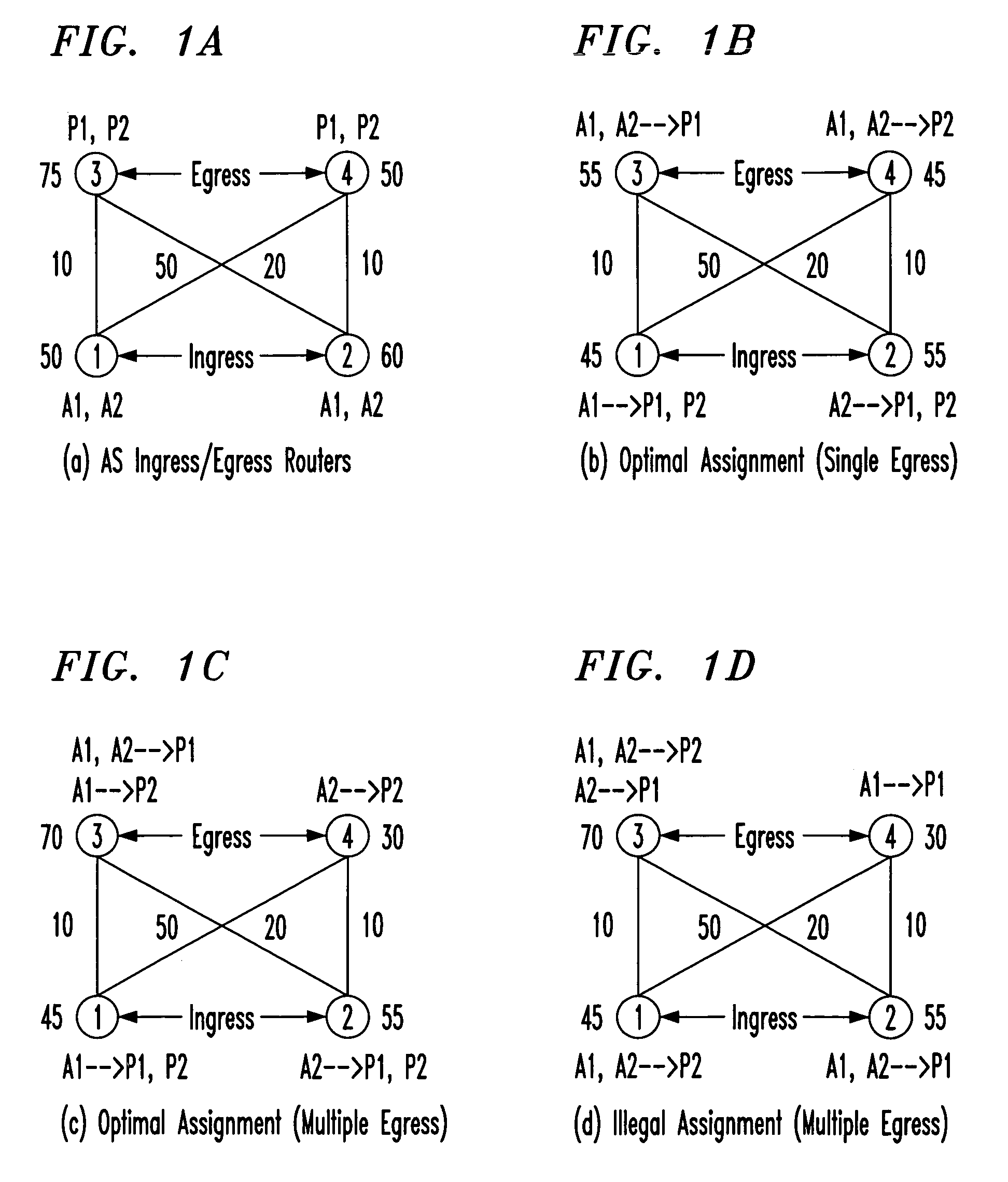
[0058]Consider the AS illustration in FIG. 1A having four border routers b1,K,b4. Routers b1 and b2 serve as ingress routers (so K1=K2=0) with capacity constraints C1=50 and C2=60, respectively. Routers b3 and b4 are egress routers (so C1=C2=0) with bandwidth constraints K3=75 and K4=50, respectively. The intra-domain distances between ingress and egress routers are as shown in FIG. 1A. Thus, d(1,3)=10 and d(1,4)=50. Two prefixes P1 and P2 are advertised at both egress routers, and so Out(1)=Out(2)={3,4}. Two AS neighbors A1 and A2 ingress data traffic through the ingress routers, so In(1)=In(2)={1,2}Finally, the amount of traffic from the AS neighbors to the destination prefixes is given by t(1,1)=t(2,2)=30,t(1,2)=15 and t(2,1)=25.
[0059]FIG. 1B depicts the optimal assignment δs for the single egress case. In the assignment, δs(1,1)=(1,3), δs(1,2)=(1,4), δs(2,1)=(2,3) and δs(2,2)=(2,4). Router b1 ingresses all the traffic from A1, while b2 ingresses all traffic from A2. Also, b3 egr...
example 2
[0077]Revisiting Example 1, consider the AS in FIG. 1. Suppose that egress router b3 is selected to egress traffic for prefix P1 and egress router b4 is chosen to egress traffic for P2. Then, the problem of computing the optimal ingress routers for traffic from ASes A1 and A2 to prefixes P1 and P2 is equivalent to GAP. In the GAP instance, there are two machines 1 and 2 corresponding to ingress routers b1 and b2 with processing times T1=C1=50 and T2=C2=60. Further, there are four jobs corresponding to (Ah,Pk) pairs (1,1), (1,2), (2,1) and (2,2). The processing time of job (1,1) on both machines is t(1,1)=30, while the processing time of job (1,2) is t(1,2)=15. The cost of processing job (1,1) on machine 2 is d(2,3)·t(1,1)=600 (since b3 is egress router for P1), while that of processing job (1,2) on machine 1 is d(1,4)·t(1,2)=750 (since b4 is egress router for P2) Clearly, the optimal assignment for the GAP instance is also the optimal cost assignment for the SES instance with egress...
PUM
Abstract
A system for, and method of, configuring border gateway selection for transit traffic flows in a computer network. In one embodiment, the system includes: (1) a border gateway modeler that builds a model of cooperating border gateways, the model including capacities of the border gateways and (2) a traffic flow optimizer, associated with the border gateway modeler, that initially assigns traffic to the border gateways in accordance with a generalized assignment problem and subsequently reassigns the traffic to the border gateways based on cost until the capacities are respected.
Description
TECHNICAL FIELD OF THE INVENTION[0001]The present invention is directed, in general, to computer networks and, more specifically, to a system and method for optimally configuring border gateway selection for transit traffic flows in a computer network.BACKGROUND OF THE INVENTION[0002]The primary responsibility of an Internet Service Provider (ISP) is to provide transit service from its set of customers to the remainder of the Internet and to bring traffic from its own upstream providers and peers destined to its customers. The interface from the ISP to the customers, upstream providers, and peers is through a set of border routers of the ISP. Currently, a border gateway protocol (BGP) allows border gateways (“border router” and “border gateway” will be used interchangeably) to be selected to carry transit traffic flows.[0003]This responsibility is balanced with an objective of the ISP to minimize the resources used on its network in carrying transit traffic. The ISP wishes to get tr...
Claims
Application Information
Patent Timeline
Application Date:The date an application was filed.
Publication Date:The date a patent or application was officially published.
First Publication Date:The earliest publication date of a patent with the same application number.
Issue Date:Publication date of the patent grant document.
PCT Entry Date:The Entry date of PCT National Phase.
Estimated Expiry Date:The statutory expiry date of a patent right according to the Patent Law, and it is the longest term of protection that the patent right can achieve without the termination of the patent right due to other reasons(Term extension factor has been taken into account ).
Invalid Date:Actual expiry date is based on effective date or publication date of legal transaction data of invalid patent.
IPC IPC(8): H04L12/28G06F15/173G06F9/46H04L12/56
CPCH04L45/04H04L45/30H04L47/125H04L47/10H04L45/38
InventorBRESSOUD, THOMAS C.RASTOGI, RAJEEVSMITH, MARK A.

