Apparatus and system for retrofitting water control valves

a technology of water control valves and apparatuses, which is applied in water supply installation, process and machine control, instruments, etc., can solve the problems of low water temperature between hot water heaters and fixtures, inability to easily drain, and inability to easily bypass cold or tepid water. , to achieve the effect of reducing electrical demand and wear, and facilitating bypassing cold or tepid water

Inactive Publication Date: 2007-04-03
GRUNDFOS PUMPS
View PDF27 Cites 29 Cited by
  • Summary
  • Abstract
  • Description
  • Claims
  • Application Information

AI Technical Summary

Benefits of technology

[0016]In one embodiment of the present invention, the apparatus and system for retrofitting water control valves is utilized to incorporate a bypass valve in the water control fixture system to automatically bypass cold or tepid water away from the hot water side of the tub / shower fixture while the temperature of the water is below the desired level so as to maintain hot water at the tub / shower water control valve when desired by the user. Although a variety of bypass valves may be used, the preferred embodiment utilizes a thermostatically controlled bypass valve having a thermally sensitive actuating element, such as a wax-filled cartridge actuator, to bypass the cold or tepid water past the tub / shower valve. The above embodiment also incorporates a self-cleaning screen disposed in the water control valve so as to keep debris out of the bypass valve. The actuating element has an actuating body and a rod member, the rod member being configured to operatively extend from the actuating body to seal against a passage located in the separating wall to prevent water flow through the passage. A bias spring is located in the bypass valve body to urge the rod member toward the actuating body so as to open the passage. A check valve can be used in the bypass valve to prevent flow of water from the cold water side to the hot water side.
[0030]It is also an objective of the present invention to provide a faucet having a thermostatically controlled bypass valve that includes a check valve in the bypass valve to prevent the flow of water from the cold water piping system to the hot water piping system when the bypass valve is cold and thus in an open condition.

Problems solved by technology

A well-known problem with most home and industrial water distribution systems is that hot water is not always readily available at the hot water side of the fixture when it is desired.
This problem is particularly acute in water use fixtures that are located a distance from the hot water heater or in systems with poorly insulated pipes.
As a result, the temperature of the water between the hot water heater and the fixture lowers until it becomes cold or at least tepid.
For certain fixtures, such as virtually all dishwashers and washing machines, there typically is no easy method of “draining” away the cold or tepid water in the hot water pipes prior to utilizing the water in the fixture.
The inability to have hot water at the hot water side of the fixture when it is desired creates a number of problems.
One problem, as described above, is having to utilize cold or tepid water when hot water is desired.
Even in those fixtures where the person can allow the cold or tepid water to flow out of the fixture until the water reaches the desired warm or hot temperature, such as a bath or shower, there are certain problems associated with such a solution.
One such problem is the waste of water that flows out of the fixture through the drain and, typically, to the sewage system.
This good and clean water is wasted, resulting in unnecessary water treatment after flowing through the sewage system.
This waste of water is compounded when the person is inattentive and hot water begins flowing down the drain and to the sewage system.
Yet another problem associated with the inability to have hot water at the hot water valve when needed is the waste of time for the person who must wait for the water to reach the desired temperature before he or she-can take a bath or shower at the desired temperature.
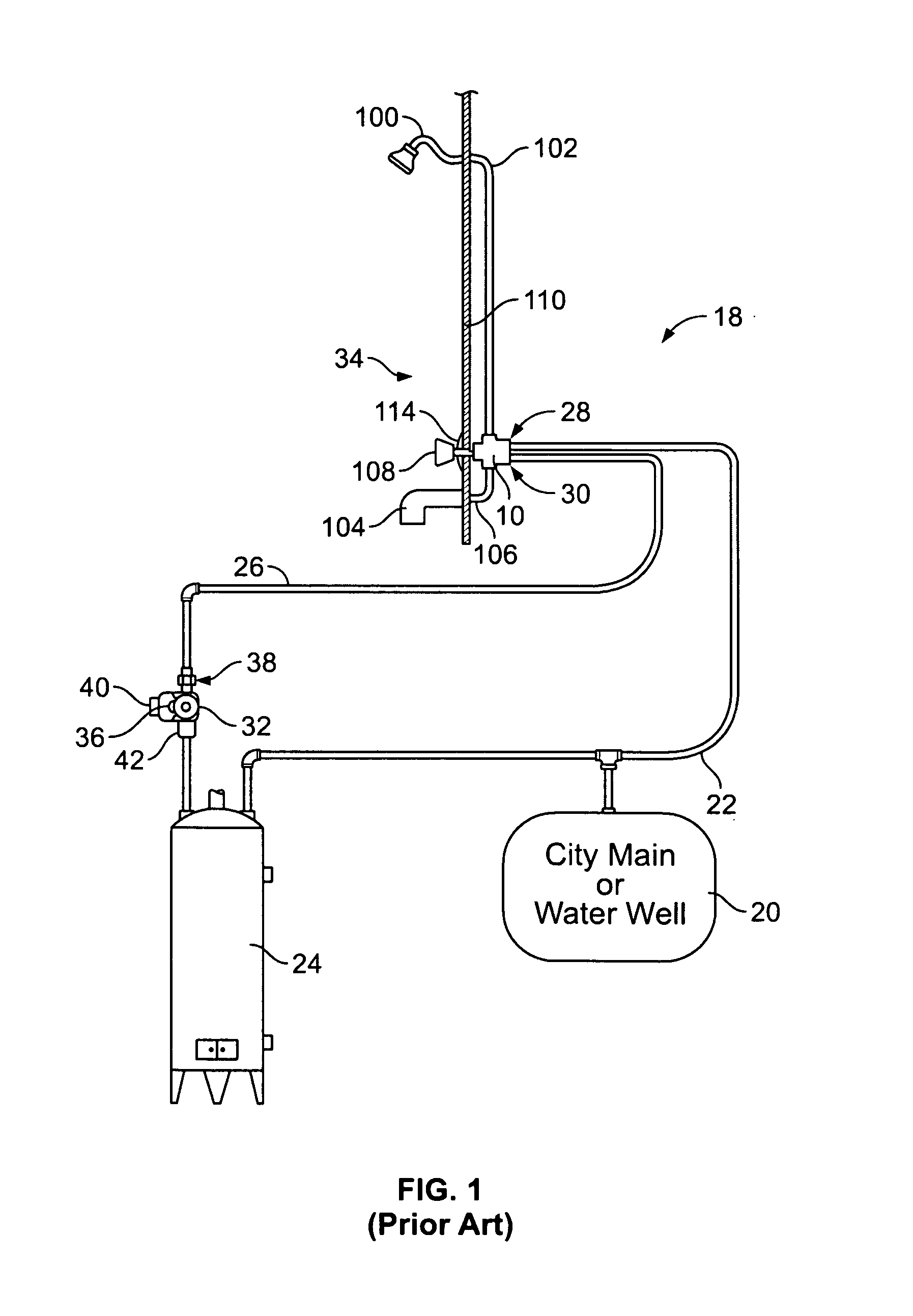
Despite the devices and systems set forth above, many people still have problems with obtaining hot water at the hot water side of fixtures, particularly bath and / or shower fixtures, located away from the hot water heater or other source of hot water.
While this meets the primary function of keeping the water at a remote fixture hot, leaving the valve in a slightly open condition does present two problems.
First, the lack of toggle action can result in scale being more likely to build up on the actuator because it is constantly extended.
Second, the open valve constantly bleeds a small amount of hot or almost hot water into the cold water piping, thereby keeping the faucet end of the cold water pipe substantially warm.
If the bypass valve is equipped with a spring-loaded check valve to prevent siphoning of cold water into the hot water side when only the hot water faucet is open, then the very small flow allowed through the throttled-down valve may cause chattering of the spring loaded check valve.
It is also detrimental to have any noticeable crossover flow (siphoning) from hot to cold or cold to hot with any combination of faucet positions, water temperatures, or pump operation.
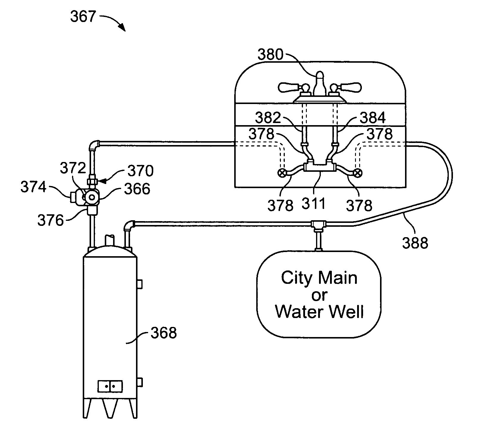
Due to the nature of their use, shower / tub fixtures are the most common problem areas with regard to the availability of hot water and, as such, can benefit greatly from the use of a bypass valve, such as a thermostatically controlled bypass valve, Unfortunately, retrofitting an attached or adjacent bypass valve to an existing shower control valve (i.e., one that is mounted into the water distribution system) has not been very practical.
Generally, existing shower control valve designs do not lend themselves to hydraulic connections through which cooled-off water may be bypassed, as is relatively easily accomplished with angle stop hose connections under a sink.
Although saddle valves could conceivably be utilized, the installation of these valves would require the gross enlargement of the opening in the shower wall.
As a result, the retrofitting of an existing tub / shower installation to incorporate a bypass valve or other beneficial hydraulic improvements, such as pressure balanced valve spools and the like, has generally been impractical with existing valves and valve systems.
Besides the currently available tub / shower water control valves, there are also a multitude of other such valves that are no longer commercially available (i.e., those replaced or upgraded with a different model).
The existence of these many different designs complicates the ability to provide an apparatus and / or system for retrofitting the tub / shower water control valve to incorporate a bypass valve or other operating improvements, such as pressure balancing.
None of the known prior art devices provide an apparatus or system that is adaptable for retrofitting the multitude of different tub / shower water-control valve designs to incorporate a bypass valve.

Method used


Image

  • Apparatus and system for retrofitting water control valves
  • Apparatus and system for retrofitting water control valves
  • Apparatus and system for retrofitting water control valves

Examples


Embodiment Construction

[0064]With reference to the figures where like elements have been given like numerical designations to facilitate the reader's understanding of the present invention, the preferred embodiments of the present invention are set forth below. The enclosed figures and drawings are illustrative of the preferred embodiments and represent a preferred way of configuring the present invention. Although specific components, materials, configurations and uses are illustrated, it should be understood that a number of variations to the components and to the configuration of those components described herein and in the accompanying figures can be made without changing the scope and function of the invention set forth herein.

[0065]In the accompanying drawings of the various preferred embodiments of a water control valve, the tub / shower water control valve is shown as 10 (i.e., FIGS. 1 and 5) and a bypass valve is shown as 16 (i.e., FIG. 2) that is adaptable for use with the apparatus and system for...


PUM


Abstract

A water control fixture having an operating valve and a thermostatically controlled bypass valve disposed in the fixture for bypassing water away from the fixture until the water temperature reaches a desired level. When pressurized water from the hot water heater reaches the desired temperature level at the fixture, the bypass valve closes and hot water is made available to the fixture. The bypass valve has a thermal actuator element that is thermally responsive to the temperature of the water. The fixture can have a housing with an interior chamber for operatively receiving the bypass valve. Various passages or channels can be provided to facilitate communication between the bypass valve and the water supply lines. Alternatively, the bypass valve can be positioned in the operating valve, including the moveable ball and the replaceable cylindrical valving cartridge types. A system using the in-fixture bypass valve is also provided.

Description

CROSS-REFERENCE TO RELATED APPLICATIONS[0001]This application claims the benefit of U.S. Provisional Application No. 60 / 465,854 filed Apr. 28, 2003, and is a continuation-in-part of U.S. patent application Ser. No. 10 / 394,795 filed Mar. 21, 2003, now U.S. Pat. No. 7,073,528 which is a continuation-in-part of 10 / 006,970 filed Dec. 4, 2001, now patented as U.S. Pat. No. 6,929,187, which is a continuation-in-part of U.S. patent application Ser. No. 09 / 697,520 filed Oct. 25, 2000, now patented as U.S. Pat. No. 6,536,464.BACKGROUND OF THE INVENTION[0002]In certain aspects, the present invention relates generally to apparatuses and systems for retrofitting water control valves used in home or industrial water distribution systems that supply water to various fixtures at different temperatures through different pipe systems. More specifically, the present invention relates to apparatuses and systems for retrofitting such water control valves to incorporate a bypass valve or other operating...

Claims


Application Information

Patent Timeline
Patent Type & Authority Patents(United States)
IPC IPC(8): F16K49/00E03B7/07E03C1/00
CPCE03B1/048E03B7/045E03B7/09G05D23/1346Y10T137/6977Y10T137/7043Y10T137/698Y10T137/6497Y10T137/5109
Inventor KEMPF, DALELUM, KEN
Owner GRUNDFOS PUMPS
Why Eureka
Try Eureka