Fuel injector with and without pressure ampification with a controllable needle speed and method for the controlling thereof

a fuel injector and needle speed technology, applied in the direction of fuel injection apparatus, combustion engine, charge feed system, etc., can solve the problems of reducing the effective brake mass, armature chatter, reducing the kinetic energy of the armature, etc., to achieve the effect of rapid relief of pressure, high speed of the nozzle needle, and more design freedom

Inactive Publication Date: 2007-04-03
ROBERT BOSCH GMBH
View PDF10 Cites 8 Cited by
  • Summary
  • Abstract
  • Description
  • Claims
  • Application Information

AI Technical Summary

Benefits of technology

[0010]In a first embodiment of the design according to the invention, the valve body can be associated with two control elements that function as actuators. One of the solenoid valves that are used as actuators can open a very small outlet throttle for a pilot injection of fuel into the combustion chamber of an autoignition internal combustion engine. The pressure oscillations produced can be kept very low by means of the quantity that the very small outlet throttle allows to flow out of the injection system comprised of the high-pressure reservoir (common rail), the supply line, and the fuel injector. The smaller these pressure oscillations can be kept, the less influence the pressure oscillations have on the possible second pilot injection or the main injection phase following the pilot injection. This gives subsequent injections a significantly greater cyclical stability with regard to the pressure increase and significantly improves the maintenance of extremely small quantities injected into the combustion chamber, i.e. the minimum quantity capacity of the fuel injector according to the invention.
[0011]Depending on the way in which the first outlet throttle and an additional, second outlet throttle are matched to each other, the second actuator embodied as a solenoid valve can be used only for the main injection or also together with the actuator that produces the pilot injection and triggers the first outlet throttle, which is very small. When both actuators are triggered, control chamber volumes can be used to relieve the pressure in the control chamber very quickly. This means that the vertical stroke motion of the injection valve element of occurs at a relatively high speed due to the pressure relief of the control chamber. A rapid opening of the injection valve element, which is embodied for example as a nozzle needle, results in the fact that during main injection phases, the jet-preparation energy does not experience any throttling action at the nozzle needle seat due to an excessively slow opening; instead, the jet-preparation energy is present at the injection opening. This means that on the one hand, the fuel injected through the injection openings into the combustion chamber of the engine enters the injection opening at a very high pressure due to the lack of throttling action and on the other hand, the fuel can be very finely vaporized, which has a favorable effect on combustion.
[0013]If the double-switching solenoid valve is triggered with a first power supply level, then a small preinjection quantity can be metered in a precise, stable fashion. If the double-switching solenoid valve is acted on with a second power supply level, though, then a rapid relief of the pressure in the control chamber can occur so that the main injection takes place at a high needle opening speed, with the attendant advantages outlined above.
[0014]In other advantageous embodiments of the invention, a pressure booster is also provided, which boosts the fuel pressure above the pressure prevailing in the high-pressure reservoir. This yields numerous additional possibilities for controlling the fuel injector. It offers the possibility of producing different speeds of the nozzle needle with a pressure boosting that can be switched during operation. This wide variability in the control of the fuel injector offers the particular advantage of the capacity to influence the movement sequence of the nozzle needle and to control the injection pressure so that it is possible to shape the injection curve by means of the triggering concept. In comparison to conventionally designed fuel injectors, the fuel injector embodied according to the invention allows for considerably more design freedom with regard to the flexibility of the injection curve and the injection pressure. In addition, it is possible to achieve a very high speed of the nozzle needle during the opening movement.
[0015]These embodiments of the invention therefore offer the possibility of an even wider variation in the speed of the nozzle needle of the fuel injector and the possibility of producing a very high injection pressure that exceeds the pressure level of a pressure reservoir even further. The high speed of the nozzle needle reduces the throttling action in the nozzle seat. Both effects lead to a very fine, uniform vaporization of fuel during the injection process and therefore to a further reduction in the emission of pollutant exhaust. Through corresponding control of the magnetic actuators, it is also easily possible to optimally adapt the curve of the injection process to the requirements of the internal combustion engine.

Problems solved by technology

The use of two-part armatures reduces their effectively braked mass and therefore reduces the kinetic energy of the armature striking the valve seat and thus causing the armature chatter.
Since they require an iterative adjustment that must be carried out in steps, these embodiments are costly, are difficult to automate, and therefore extend the cycle times that the manufacture of such solenoid valves requires.
These components, however, only permit the achievement of very low opening and closing speeds of an injection valve element, which can be embodied as a nozzle needle.
In multiple injections, it is therefore not possible to use different needle opening speeds to influence the pressure increase, which is decisive with regard to emissions, in such a way that a pilot injection (PI) occurs very close to the main injection phase without influencing the subsequent injections in a functionally critical manner.

Method used


Image

  • Fuel injector with and without pressure ampification with a controllable needle speed and method for the controlling thereof
  • Fuel injector with and without pressure ampification with a controllable needle speed and method for the controlling thereof
  • Fuel injector with and without pressure ampification with a controllable needle speed and method for the controlling thereof

Examples


Embodiment Construction

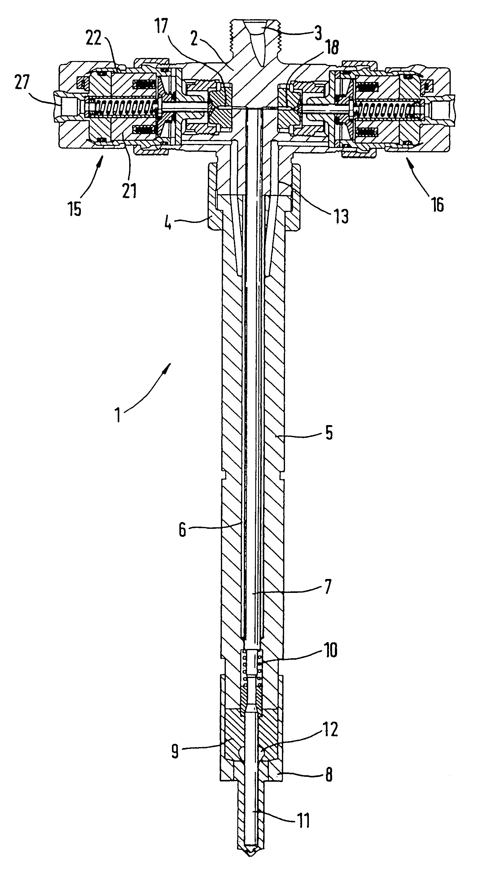
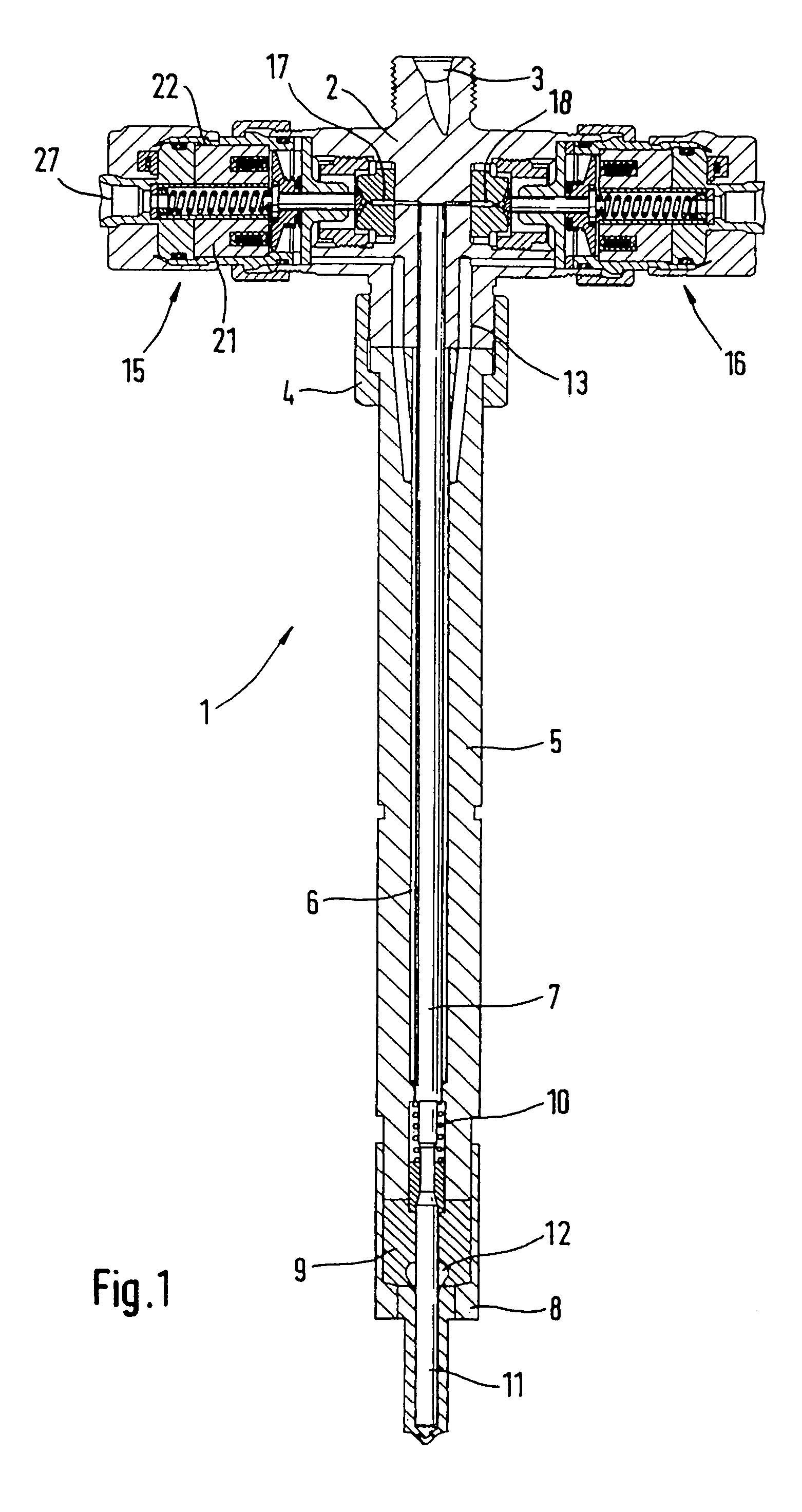
[0031]FIG. 1 shows a fuel injector 1, which has a valve body 2 to which a holding body 5 is fastened by means of a clamping nut 4. The holding body 5 has a central bore 6 that contains a push rod 7 that extends in the valve body 2 and through the holding body 5. The lower end of the holding body 5, which is interchangeably fastened to the valve body 2 by means of the clamping nut 4, accommodates a nozzle retaining nut 8, which in turn contains a nozzle body 9. The nozzle retaining nut 8 serves to screw the lower end of the holding body 5 to the nozzle body 9. The transition region between the lower end of the holding body 5 and the upper region of the nozzle body 9 contains a closing spring 10, which encompasses the lower end of the push rod 7 and acts on a vertically moving injection valve element 11 contained in the nozzle body 9. The injection valve element 11 is preferably embodied as a nozzle needle and, in the region of a pressure shoulder, is encompassed by nozzle chamber 12....


PUM


Abstract

A fuel injector in injection systems for internal combustion engines having a valve body containing a control chamber that can be pressure-relieved and can be acted on with fuel via an inlet throttle and can be pressure-relieved via an outlet throttle. A first actuator can actuate a closing element. The valve body is connected to a holding body that has a nozzle body connected to it, which encompasses an injection valve element. In order to relieve the pressure in the control chamber, an additional, second outlet throttle is provided, whose closing element can be actuated either by an additional actuator or as a function of the power supply to a double-switching actuator.

Description

CROSS-REFERENCE TO RELATED APPLICATIONS[0001]This application is a 35 USC 371 application of PCT / DE 03 / 02317 filed on Jul. 10, 2003.BACKGROUND OF THE INVENTION[0002]1. Field of the Invention[0003]Fuel injectors of internal combustion engines execute a stroke-controlled or pressure-controlled injection of highly pressurized fuel into the combustion chamber of an engine. In order to comply with current and future exhaust regulations for internal combustion engines, it has become necessary to execute multiple injections (preinjections, main injections, and secondary injections). The time interval between these individual injections should be as short as possible and should at the same time exert as little influence as possible on the subsequent injection. A pilot injection, which precedes the main injection phase and is intended for conditioning the combustion chamber should not influence a subsequent main injection phase with regard to the pressure increase relevant to emissions.[0004...

Claims


Application Information

Patent Timeline
Patent Type & Authority Patents(United States)
IPC IPC(8): F02M41/16F02M45/02F02M47/00F02M45/08F02M45/12F02M47/02F02M57/02F02M59/10F02M59/46F02M61/20F02M63/00
CPCF02M45/02F02M45/08F02M45/12F02M47/027F02M57/025F02M59/105F02M63/0015F02M63/0017F02M63/0026F02M63/004F02M63/0043F02M63/0049F02M63/0064F02M61/205F02M63/0022F02M47/02F02M59/46F02M61/10
Inventor BRENK, ACHIMKROPP, MARTINMACK, MANFREDHAMMER, JUERGENTAMPE, REINHARDBASTIAN, HEIKE
Owner ROBERT BOSCH GMBH
Why Eureka
Try Eureka