Tread for a tire having a rigidity gradient

a technology of rigidity gradient and tread, which is applied in the direction of tyre tread bands/patterns, tire parts, vehicle components, etc., can solve the problems of increasing production costs, unsatisfactory performance, and complex manufacturing of composite treads, and achieves simple and economical effects

Inactive Publication Date: 2007-04-03
MICHELIN RECH & TECH SA
View PDF16 Cites 80 Cited by
  • Summary
  • Abstract
  • Description
  • Claims
  • Application Information

AI Technical Summary

Benefits of technology

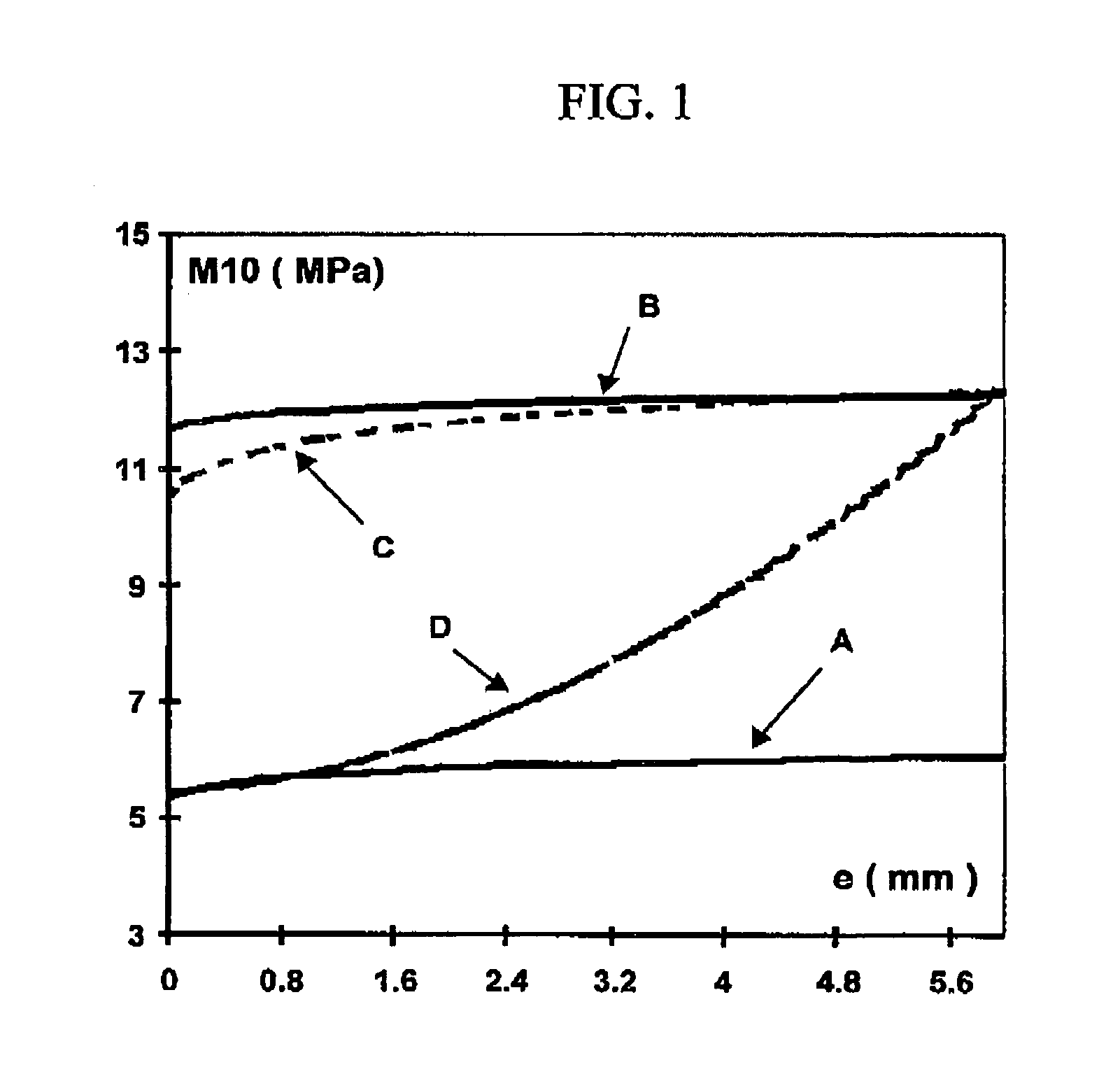
[0017]Now, the Applicants have discovered during their research that a specific rubber composition, based on a high amount of reinforcing inorganic filler and a methylene acceptor / donor system, makes it possible, owing to an unexpected “auto-accommodation” phenomenon, to obtain a tread having a true rigidity gradient, radially increasing from the surface towards the inside of the tread. This rigidity gradient is not only obtained simply and economically, but also durably, thus making it possible to keep the compromise between grip and road behaviour of the tires at a very high level, throughout the life of the latter.

Problems solved by technology

However, such stiffening of the tread, at the very least for its surface part which is in contact with the ground during running of the tire, in known manner impairs, most frequently in crippling manner, the properties of grip on wet, snow-covered or icy ground.
Such a solution however has numerous disadvantages:first of all, the manufacturing of a composite tread is by definition more complex and therefore more costly than that of a conventional tread, and requires in particular the use of complex coextrusion machines;during manufacturing, after cutting out the tread to the correct dimensions once it has emerged from the extruder, it is furthermore necessary to manage discarding of material of different natures, which further substantially increases the production costs;finally, and this is not the least of the disadvantages, once the radially outer (flexible) part of the tread has become worn, it is the initially inner part of the tread which comes into contact with the road: then, of course, one has the disadvantages of an excessively rigid tread, with unsatisfactory performance from the point of view of the technical compromise initially intended.

Method used


Image

  • Tread for a tire having a rigidity gradient
  • Tread for a tire having a rigidity gradient

Examples


Embodiment Construction

I. Measurements and Tests Used

[0041]The treads and rubber compositions constituting these treads are characterised, before and after curing, as indicated hereafter.

[0042]I-1. Mooney plasticity. An oscillating consistometer such as described in French Standard NF T 43-005 (November 1980) is used. The Mooney plasticity is measured in accordance with the following principle: the raw composition (i.e. before curing) is moulded in a cylindrical enclosure heated to 100° C. After one minute's preheating, the rotor turns within the test piece at 2 rpm, and the torque used for maintaining this movement is measured after four minutes' rotation. The Mooney plasticity (ML 1+4) is expressed in “Mooney units” (MU, with 1 MU=0.83 Newton.meter).

[0043]I-2. Scorching time. The measurements are effected at 130° C., in accordance with French Standard NF T 43-005. The evolution of the consistometric index as a function of time makes it possible to determine the scorching time for the rubber compositions...


PUM

PropertyMeasurementUnit
temperatureaaaaaaaaaa

Abstract

A tire tread comprising a rubber composition based on (phr: parts by weight per hundred parts of elastomer):
    • (i) a diene elastomer;
    • (ii) more than 50 phr of an inorganic filler as reinforcing filler;
    • (iii) between 2 and 15 phr of an (inorganic filler/diene elastomer) coupling agent;
    • (iv) between 1 and 10 phr of a methylene acceptor, and
    • (v) between 0.5 and 5 phr of a methylene donor.
This tread has, after mechanical running-in of the tire for which it is intended (“auto-accommodation”), a rigidity gradient which increases radially from the surface towards the inside of the tread. Use of such a tread for the manufacturing or recapping of tires. Tires comprising a tread according to the invention, in particular of the snow or ice type (“winter” tires).

Description

[0001]The present application is a continuation of International Application No. PCT / EPO1 / 08566, filed 25 Jul. 2001, published in French with an English Abstract on 7 Feb. 2001, under PCT Article 21(2), which claims priority to French Patent Application No. FR00 / 10094, filed 31 Jul. 2000.BACKGROUND OF THE INVENTION[0002]1. Field of the Invention[0003]The present invention relates to treads for tires and to rubber compositions used for the manufacturing of such treads.[0004]It relates more particularly to treads for tires having a low rolling resistance, reinforced majoritarily by reinforcing inorganic fillers such as siliceous or aluminous fillers, these treads being intended in particular for tires fitted on vehicles such as motorcycles, passenger cars, vans or heavy vehicles.[0005]2. Description of the Related Art[0006]Since fuel economies and the need to protect the environment have become priorities, it has proved necessary to produce tires having reduced rolling resistance. Thi...

Claims


Application Information

Patent Timeline
Patent Type & Authority Patents(United States)
IPC IPC(8): B60C1/00C08K3/04C08K3/36C08J3/20C08K3/00C08K5/54C08L9/00C08L9/04C08L9/06
CPCB60C1/0016C08K3/36C08L9/04C08L9/06B60C11/005C08L9/00C08L61/06Y10S152/905C08L2666/16C08L2666/02
Inventor VASSEUR, DIDIER
Owner MICHELIN RECH & TECH SA
Why Eureka
Try Eureka