Method of operating a secondary battery system having first and second tanks for reserving electrolytes

Inactive Publication Date: 2007-04-03
SUMITOMO ELECTRIC IND LTD +1
View PDF3 Cites 61 Cited by
  • Summary
  • Abstract
  • Description
  • Claims
  • Application Information

AI Technical Summary

Benefits of technology

[0020]Valves are preferably used as the switching means. Preferably, the secondary battery system comprises an association mechanism for controlling the switching means on the side on which the electrolytes are discharged from the first tanks or the second tanks and the switching means on the side on which the electrolytes are fed to the first tanks or the second tanks in association with each other. This associated switching operation can allow balancing of a quantity of electrolytes discharged from the tanks and a quantity of electrolytes fed to the tanks at the switching of the tanks, to prevent imbalance of quantity of electrolytes in the cell or generation of considerable pressure c

Problems solved by technology

Due to this, even when a large quantity of electrolyte of a low state of charge i

Method used


Image

  • Method of operating a secondary battery system having first and second tanks for reserving electrolytes
  • Method of operating a secondary battery system having first and second tanks for reserving electrolytes
  • Method of operating a secondary battery system having first and second tanks for reserving electrolytes

Examples


Example

[0031](First Embodiment)

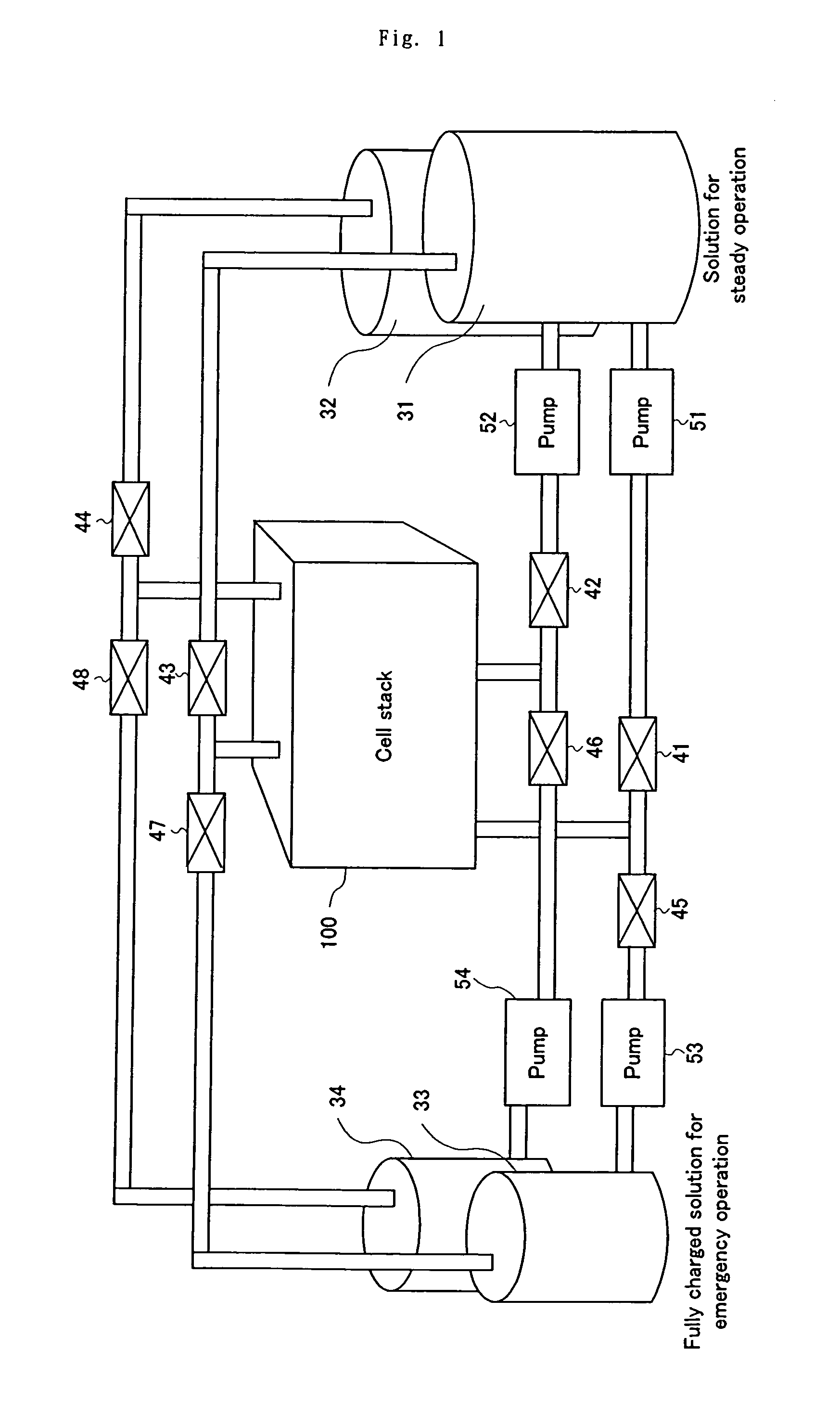
[0032]FIG. 1 is a diagrammatic illustration of construction of a redox flow battery system of the present invention.

[0033]This battery system comprises a single cell stack 100, two sets of tanks 31, 32 and 33, 34 for reserving electrolytes, valves 41–48 for allowing switching of the electrolytes contained in the tanks 31–34, to selectively supply the electrolytes to the cell stack 100, and pumps 51–54 for circulating the electrolytes.

[0034]The cell stack 100 is identical in construction to the conventional one, as illustrated in FIGS. 6 and 7.

[0035]The tanks 31–34 comprise the first tanks 31, 32 for supplying the electrolytes to the cell stack for the purpose of load-leveling during the steady operation and the second tanks 33, 34 for supplying the electrolytes to the cell stack in an emergency operation, such as during the time of electric power failure. The first tanks and the second tanks comprise positive electrolyte tanks 31, 33 and negative electrolyte ...

Example

[0044](Second Embodiment)

[0045]While in the first embodiment, the pumps 51, 52 and the pumps 53, 54 are placed for the electrolytes of the first tanks 31, 32 and the second tanks 33, 34, respectively, the pumps for each set of tanks may be combined for common use. FIG. 4 is a diagrammatic illustration of a part of a shared-pump type of redox flow battery system of the present invention. In this illustration, like reference characters refer to corresponding parts of FIG. 1.

[0046]As illustrated, pumps 55, 56 are interposed between an intermediate part of piping between the valves 41, 45 and the cell stack 100 and between an intermediate part of piping between the valves 42, 46 and the cell stack 100, respectively, for connection between the valves and the cell stack. This can allow selective switching between the electrolytes in the first tanks and the electrolytes in the second tanks and circulation of the selected electrolytes by using a total of two pumps 55, 56.

[0047]The switching...

Example

[0048](Third Embodiment)

[0049]Further, a diagrammatic illustration of a part of a redox flow battery system having a plurality of cell stacks 100–102 is shown in FIG. 5. In this third embodiment as well, the selective switching between the electrolytes in the first tanks and the electrolytes in the second tanks is controlled by the valves 41–48 being opened and closed in the same manner as in the first embodiment. Thus, the high overload operation can be provided, regardless of the state of charge of the electrolytes in the first tanks.

Capabilities of Exploitation in Industry

[0050]As described above, according to the battery of the present invention, there are provided specific tanks for storing the electrolytes that are constantly kept in the substantially fully charged state, in addition to the tanks for electrolytes for used in the steady load-leveling operation. This can provide the result that in case of emergency, the required electrolytes can be fed from those specific tanks ...


PUM


Abstract

The invention provides a secondary battery system that allows a high overload operation regardless of discharging condition during a steady operation, and an operating method thereof. The secondary battery system comprises first tanks 31, 32 for reserving electrolytes required for a steady operation, and second tanks 33, 34 for reserving electrolytes required for an emergency operation. Valves 41–48 are opened and closed for allowing selective switching between the electrolytes in the first tanks 31, 32 and the electrolytes in the second tanks 33, 34 to circulate the selected electrolytes through a cell stack 100. The electrolytes reserved in the second tanks 33, 34 are electrolytes having a proportion of a quantity of active material produced in a charging reaction to a total quantity of active material of not less than 50%.

Description

TECHNICAL FIELD[0001]The present invention relates to a secondary battery system and, more particularly, to a redox flow battery that can allow a high overload operation even in case of emergency such as electric power failure.BACKGROUND ART[0002]FIG. 6 is an explanatory view showing an operating principle of a redox flow battery. As illustrated therein, the redox flow battery has a cell 1 separated into a positive electrode cell 1A and a negative electrode cell 1B by a membrane 4 of an ion-exchange membrane. The positive electrode cell 1A and the negative electrode cell 1B include a positive electrode 5 and a negative electrode 6, respectively. A positive electrode tank 2 for feeding and discharging positive electrolytic solution to and from the positive electrode cell 1A is connected to the positive electrode cell 1A through conduit pipes 7, 8. Similarly, a negative electrode tank 3 for feeding and discharging negative electrolytic solution to and from the negative electrode cell ...

Claims


Application Information

Patent Timeline
IPC IPC(8): H01M10/44H01M8/04H01M8/18H01M50/77
CPCH01M2/40H01M8/04186H01M8/188Y02E60/528H01M8/04276Y02E60/50Y02E60/10H01M50/77Y02P70/50
Inventor TSUTSUI, YASUMITSUTOKUDA, NOBUYUKI
Owner SUMITOMO ELECTRIC IND LTD
Why Eureka
Try Eureka