Eliminating ESD exposure for read/write head with heating element

a technology of esd and read/write heads, applied in the field of recording systems, can solve the problems of lube degradation, possible esd events or other adverse consequences of tribocharging

Inactive Publication Date: 2007-04-03
WESTERN DIGITAL TECH INC
View PDF6 Cites 24 Cited by
  • Summary
  • Abstract
  • Description
  • Claims
  • Application Information

AI Technical Summary

Benefits of technology

[0004]Embodiments of the present invention provide a grounded conductive layer between the heater and the lower MR shield in the read / write head structure. The grounded conductive layer eliminates or at least substantially prevents the accumulation of charges on the lower MR shield as a result of the voltage supplied to the heater.
[0007]In specific embodiments, the plurality of read / write components comprise a magnetoresistive read assembly having a first shield, a second shield, and a magnetoresistive sensing member disposed between the first shield and the second shield; and the grounded conductive layer is disposed between the heater and the first magnetic shield. The plurality of read / write components comprise a magnetoresistive read assembly having a first shield, a second shield, and a magnetoresistive sensing member disposed between the first shield and the second shield, which are exposed on the same side as the side with the air bearing surface of the magnetic head; and an inductive write assembly having a first pole piece and a second pole piece, which are exposed on the same side as the side with the air bearing surface. The heater is encapsulated in an insulating material and spaced from the plurality of read / write components, and the heater is not exposed on the same side as the side with the air bearing surface of the magnetic head. The heater has a ground end and the grounded conductive layer is connected to the ground end of the heater or it may be grounded through any other connection as long as it is grounded to the same power source of the heater. In a preferred embodiment, the ground plane will likely be larger than the heater in planar dimension to eliminate leakage through fringe fields.
[0009]In some embodiments, a second grounded conductive layer is disposed between the heater and the slider. The second grounded conductive layer is encapsulated in an insulating material and spaced between the heater and the slider, and the second grounded conductive layer is not exposed on the same side as the side with the air bearing surface of the magnetic head. The second grounded conductive layer is at least as large in planar dimension as the heater to block influence of the heater on the slider. In a preferred embodiment, the ground plane will likely be larger than the heater in planar dimension to eliminate leakage through fringe fields.

Problems solved by technology

This may cause some charges to appear on the lower MR (magnetoresistive) shield of the MR read assembly of the head structure, which is exposed to the disk surface of the magnetic disk separated by the carbon overcoat and air.
The presence of the charges may give rise to an ESD event between the lower MR shield and the disk surface or cause charging of the disk surface resulting in possible ESD events or other adverse consequences of tribocharging such as lube degradation.

Method used


Image

  • Eliminating ESD exposure for read/write head with heating element
  • Eliminating ESD exposure for read/write head with heating element
  • Eliminating ESD exposure for read/write head with heating element

Examples


Embodiment Construction

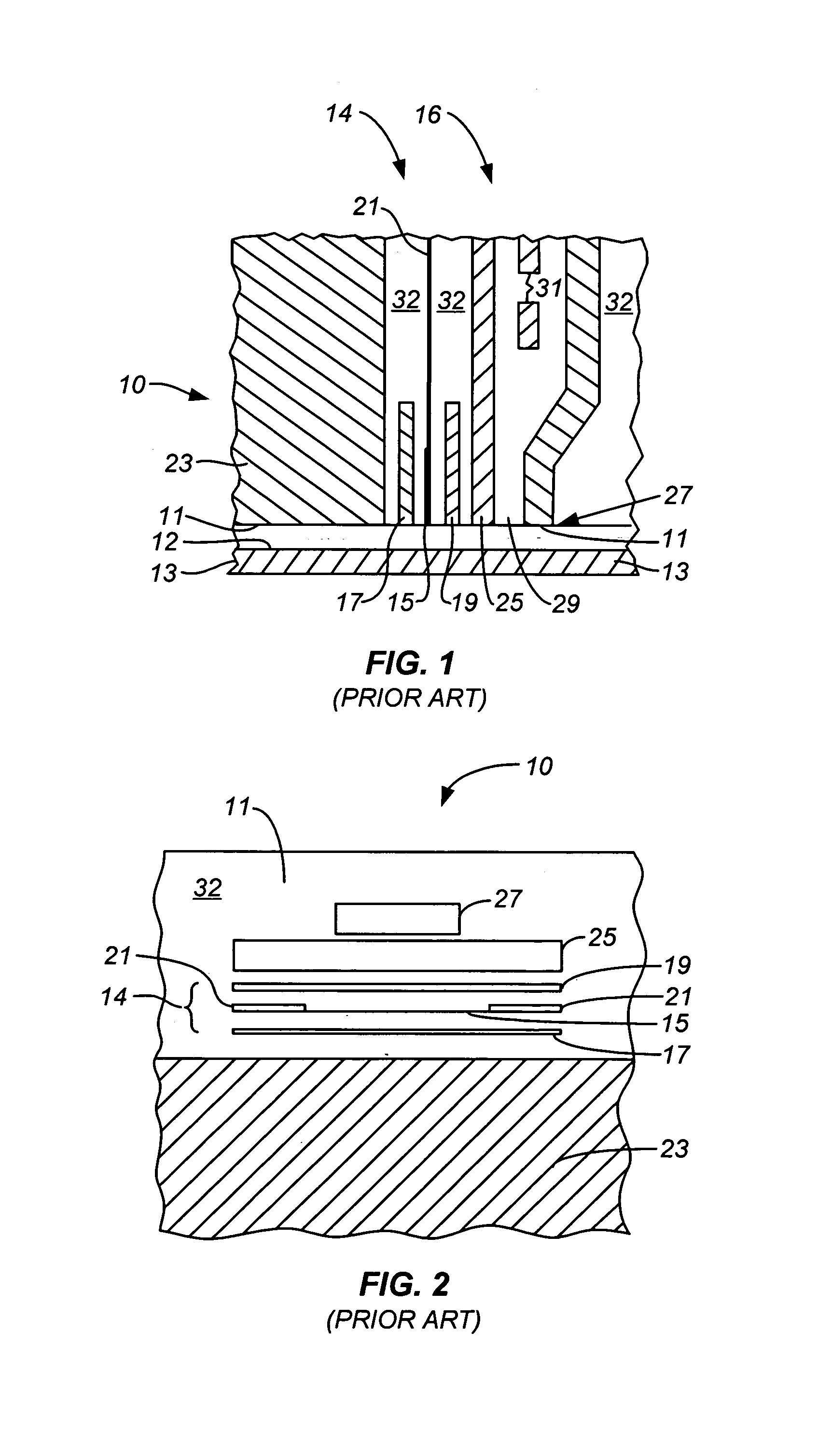
[0016]FIGS. 1 and 2 show a typical magnetoresistive (MR) read / inductive write magnetic head 10 in transducing relationship with a rotating magnetic recording disk 13 such that an air bearing surface (ABS) 11 is disposed in facing relationship with, and slightly above, a disk recording surface 12 of the recording disk 13. Typically, such a head 10 includes an MR read assembly 14 and an inductive write assembly 16 formed adjacent one another on a substrate 23. FIG. 2 is a plan view of the magnetic head 10 viewed facing the ABS 11, illustrating the magnetic head elements in the form of head read / write elements exposed on the same side as the side with the ABS 11.

[0017]The MR read assembly 14 includes an MR sensing element 15 fabricated of a ferromagnetic material, such as a nickel iron (NiFe) alloy, situated between the first or lower magnetic shield element 17 and the second or upper magnetic shield element 19. The MR sensing element 15 may include a single layer of NiFe, commonly ref...


PUM

PropertyMeasurementUnit
thicknessaaaaaaaaaa
thicknessaaaaaaaaaa
flying heightaaaaaaaaaa

Abstract

Embodiments of the present invention provide a grounded conductive layer between the heater and the lower magnetoresistive (MR) shield in the read / write head structure. The grounded conductive layer eliminates or at least substantially prevents the accumulation of charges on the lower MR shield as a result of the voltage supplied to the heater. In one embodiment, a magnetic head comprises a plurality of read / write components; a heater disposed near the plurality of read / write components; and a grounded conductive layer disposed between the heater and the plurality of read / write components.

Description

CROSS-REFERENCES TO RELATED APPLICATIONS[0001]NOT APPLICABLEBACKGROUND OF THE INVENTION[0002]This invention relates generally to recording systems and, more particularly, to eliminating ESD (electrostatic discharge) exposure for read / write heads with heating elements and tribocharging at the head / disk interface.[0003]Current read / write heads with TFC (thermal flying-height control) technology utilizes a heater integrated near the read / write head structure to control the spacing between the read / write element and the magnetic recording disk. If a single ended power supply is used to power the heater, the mean voltage at the heater will not be zero. This may cause some charges to appear on the lower MR (magnetoresistive) shield of the MR read assembly of the head structure, which is exposed to the disk surface of the magnetic disk separated by the carbon overcoat and air. The presence of the charges may give rise to an ESD event between the lower MR shield and the disk surface or caus...

Claims


Application Information

Patent Timeline
Patent Type & Authority Patents(United States)
IPC IPC(8): G11B5/56
CPCG11B5/11G11B5/314G11B5/40G11B5/6064G11B5/41
Inventor SUK, MIKE
Owner WESTERN DIGITAL TECH INC
Why Eureka
Try Eureka