Digital protection relay with time sync function

a digital protection relay and time sync technology, applied in the field of digital protection relays, can solve the problems of erroneous sampling timing, reference timing may be recognized, sampling timing of electricity data becomes erroneous, etc., and achieve the effect of eliminating an error in sampling timing

Inactive Publication Date: 2007-04-03
KK TOSHIBA
View PDF17 Cites 3 Cited by
  • Summary
  • Abstract
  • Description
  • Claims
  • Application Information

AI Technical Summary

Benefits of technology

[0011]The present invention aims at solving the above problem, and the object of this invention is to provide a digital protection relay with a time sync function, which can exactly transmit, when a reference timing is to be transmitted from a time signal generator to time sync means within the protection relay, the reference timing even if noise occurs or the signal quality deteriorates, and which can also eliminate an error in sampling timing of quantity of electricity data and correctly recognize the presence / absence of occurrence of a fault in a power system.

Problems solved by technology

However, if the pulse signal input to the reception circuit 21 deteriorates due to noise occurring in the course of communication or degradation in the communication medium L such as transmission / reception elements or cables, the magnitude of the signal varies over the determination threshold value at a timing differing by ΔT from the reference timing, as shown in FIG. 2, and the reference timing may erroneously be recognized.
As a result, the sampling timing of the quantity of electricity data becomes erroneous.
In particular, in the case where the presence / absence of a fault in the power system is determined by comparison with quantity of electricity data sampled at different locations in the power system at the same time, a fault, which has not occurred in fact, may be erroneously recognized, or a fault, which has actually occurred, may not be recognized.

Method used


Image

  • Digital protection relay with time sync function
  • Digital protection relay with time sync function
  • Digital protection relay with time sync function

Examples


first embodiment

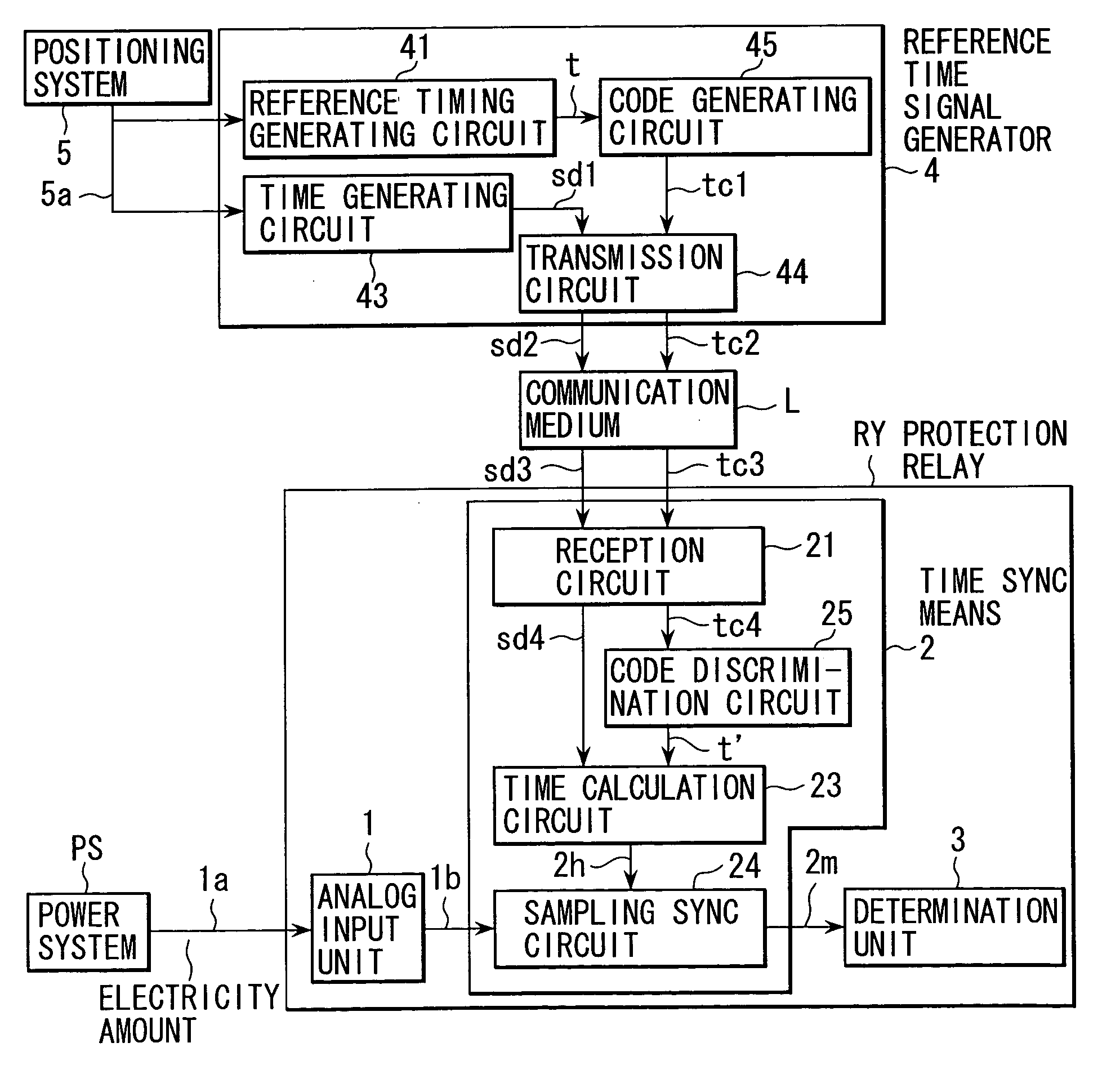
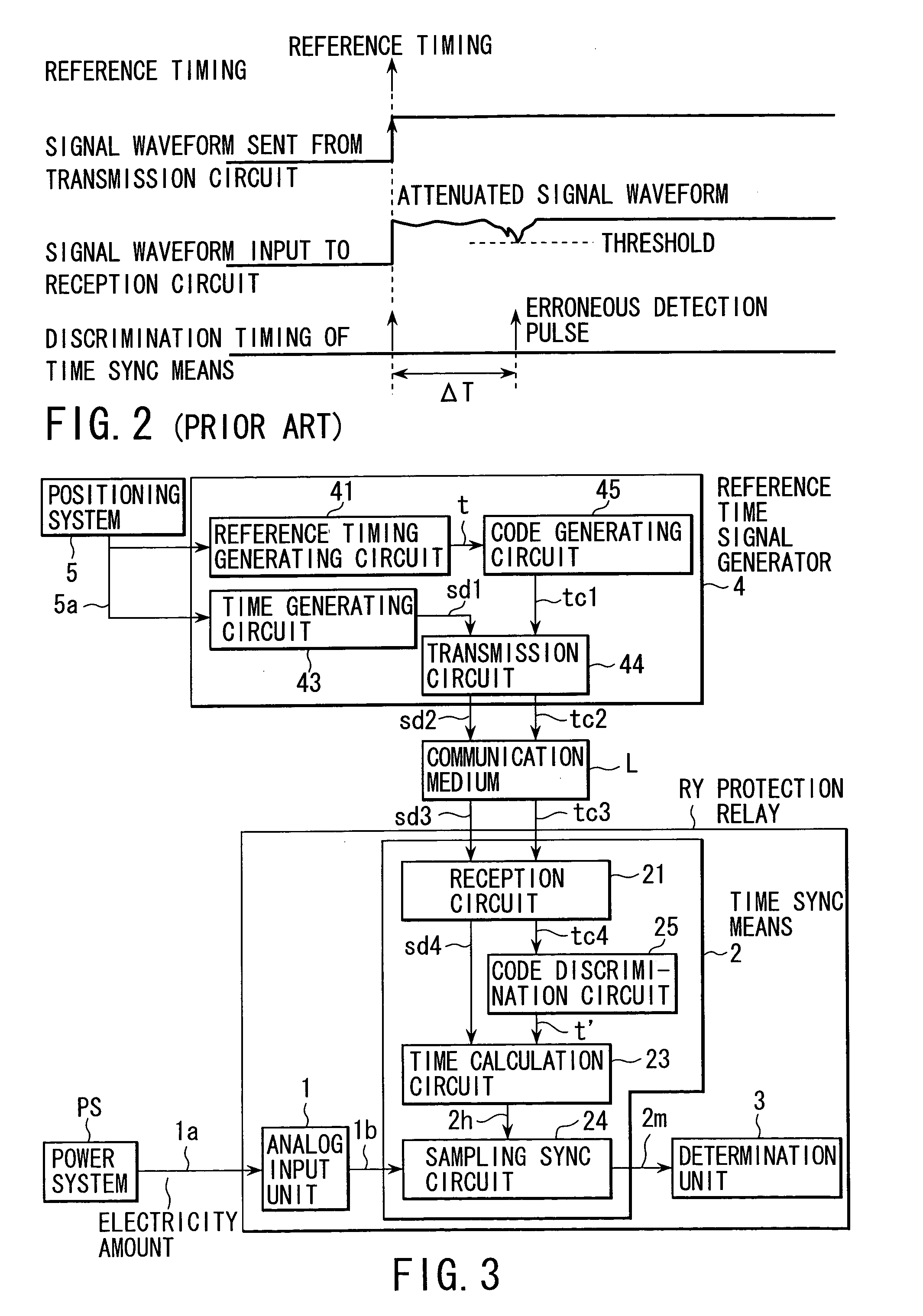
[0033]FIG. 3 is a block circuit diagram showing a digital protection relay with a time sync function according to the present invention. The parts common to those in FIG. 1 are denoted by like reference numerals.

[0034]In FIG. 3, symbol RY denotes a digital protection relay. The digital protection relay RY includes an analog input unit 1 that samples an quantity of electricity 1a input from a power system PS at predetermined cycles and converts the analog amount to a digital amount; time sync means 2 that receives a digital quantity of electricity 1b obtained by the analog input unit 1; and a determination unit 3 that compares a digital quantity of electricity 2m output from the time sync means 2 with a determination value and discriminates the presence / absence of a fault in the power system.

[0035]The time sync means 2 includes a reception circuit 21 that receives a discrimination code tc3 and time data sd3 from a reference time signal generator 4 (to be described later in detail) vi...

second embodiment

[0064]FIG. 10 is a block circuit diagram showing the digital protection relay with a time sync function according to the present invention. The parts common to those in FIG. 3 are denoted by like reference numerals, and a description thereof is omitted. Only different parts are described.

[0065]The structure of the second embodiment differs from the structure shown in FIG. 3 in the following respects. A time signal generator TS is provided with a superimposed circuit 46 that superimposes the discrimination code tc1 output from the code generating circuit 45 with the time data sd1 output from the time generating circuit 43. In addition, in the time sync means 2 of the protection relay RY, the code discrimination circuit in FIG. 3 is replaced with a collation circuit 26 that receives a reception signal mx4, which is the superimposed signal from the reception circuit 2, and a code separation circuit 27 that receives an output signal mx4f of the collation circuit 26.

[0066]The superimpose...

third embodiment

[0092]The third embodiment is configured such that the time sync means 2 shown in FIG. 3 includes a soundness monitoring circuit 26 for monitoring the soundness of at least one of the transmission circuit 44 of time signal generator 4, the communication medium L and the reception circuit 21, on the basis of the state of at least one of the time signal sd4 and discrimination code tc4, which are digital values output from the reception circuit 21.

[0093]To monitor the soundness, in this context, means to detect the presence / absence of degradation in the transmission circuit, communication medium or reception circuit, as is described later.

[0094]The operation of the soundness monitoring circuit 26 is described referring to a flow chart of FIG. 16. This flow chart is applicable to both the time signal sd4 and discrimination code tc4, which are digital values. In this description, these signal and code are generally referred to as digital values.

[0095]In step S11, digital values output fr...


PUM


Abstract

In a digital protection relay with a time sync function, the sampling timing of which is specified based on a reference timing transmitted from a time signal generator to a time sync unit, with a determination value. The time sync unit includes a reception circuit that receives a discrimination code and time data transmitted from the time signal generator, a code discrimination circuit that discriminates the reference timing on condition that the received discrimination code coincides with a desired code, a time calculation circuit that calculates the sampling timing on the basis of the discriminated reference timing and the time data, and a sampling sync circuit that specifies the sampling timing of a digital quantity of electricity on the basis of the calculated sampling timing.

Description

BACKGROUND OF THE INVENTION[0001]1. Field of the Invention[0002]The present invention relates to a digital protection relay including a time sync function.[0003]2. Description of the Related Art[0004]FIG. 1 shows a circuit configuration of a conventional digital protection relay.[0005]In FIG. 1, a digital protection relay RY includes an analog input unit 1 that samples an quantity of electricity 1a input from a power system PS at predetermined cycles and converts the analog amount to a digital amount; time sync means 2 that receives a digital quantity of electricity 1b obtained by the analog input unit 1; and a determination unit 3 that compares a digital quantity of electricity 2m output from the time sync means 2 with a determination value and discriminates the presence / absence of a fault in the power system.[0006]The time sync means 2 includes a reception circuit 21 that receives a reception pulse signal tp3 indicative of a reference timing and time data sd3, which are sent from ...

Claims


Application Information

Patent Timeline
Patent Type & Authority Patents(United States)
IPC IPC(8): H02H3/00G01R31/00G01S19/24G01S19/36H02H1/00H02H3/02H02H7/26
CPCH02H7/261H02H1/0092
Inventor ITAGAKI, DAIJUAYAKAWA, HIROAKISHUTO, ITSUO
Owner KK TOSHIBA
Why Eureka
Try Eureka