Pattern recognition apparatus and method using distributed model representation of partial images

Inactive Publication Date: 2007-04-03
KK TOSHIBA
View PDF9 Cites 13 Cited by
  • Summary
  • Abstract
  • Description
  • Claims
  • Application Information

AI Technical Summary

Benefits of technology

[0019]The present invention enables distributed model representation based on partial patterns using a hash table and efficient pattern search.
[0020]The present invention also enables high-speed search of partial patterns, detection of correct position and orientation of an object and identificat

Problems solved by technology

Although the geometric hashing method is suitable for for detecting geometrically represented objects, it is difficult to detect objects with texture, for example, complicated objects with intensity change information such as eye, nose and mouth parts and shadows on the cheek as in a face shown in FIG. 2-201.
In this case, it is difficult to represent a facial model o

Method used


Image

  • Pattern recognition apparatus and method using distributed model representation of partial images
  • Pattern recognition apparatus and method using distributed model representation of partial images
  • Pattern recognition apparatus and method using distributed model representation of partial images

Examples


Example

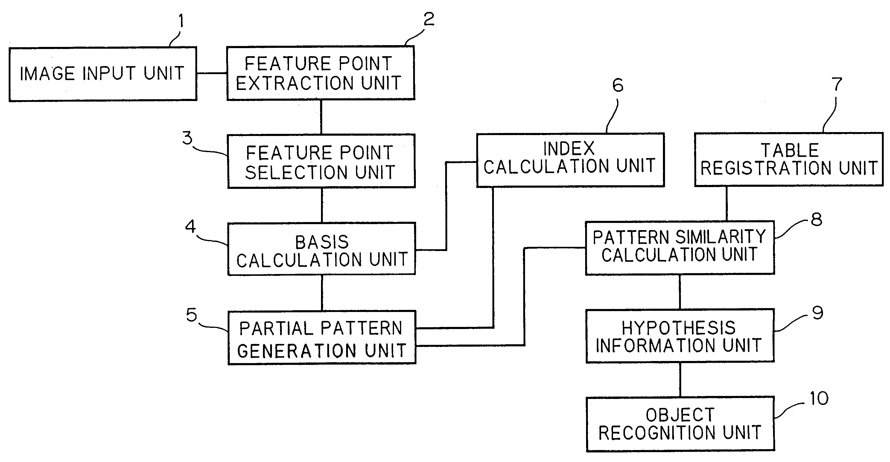
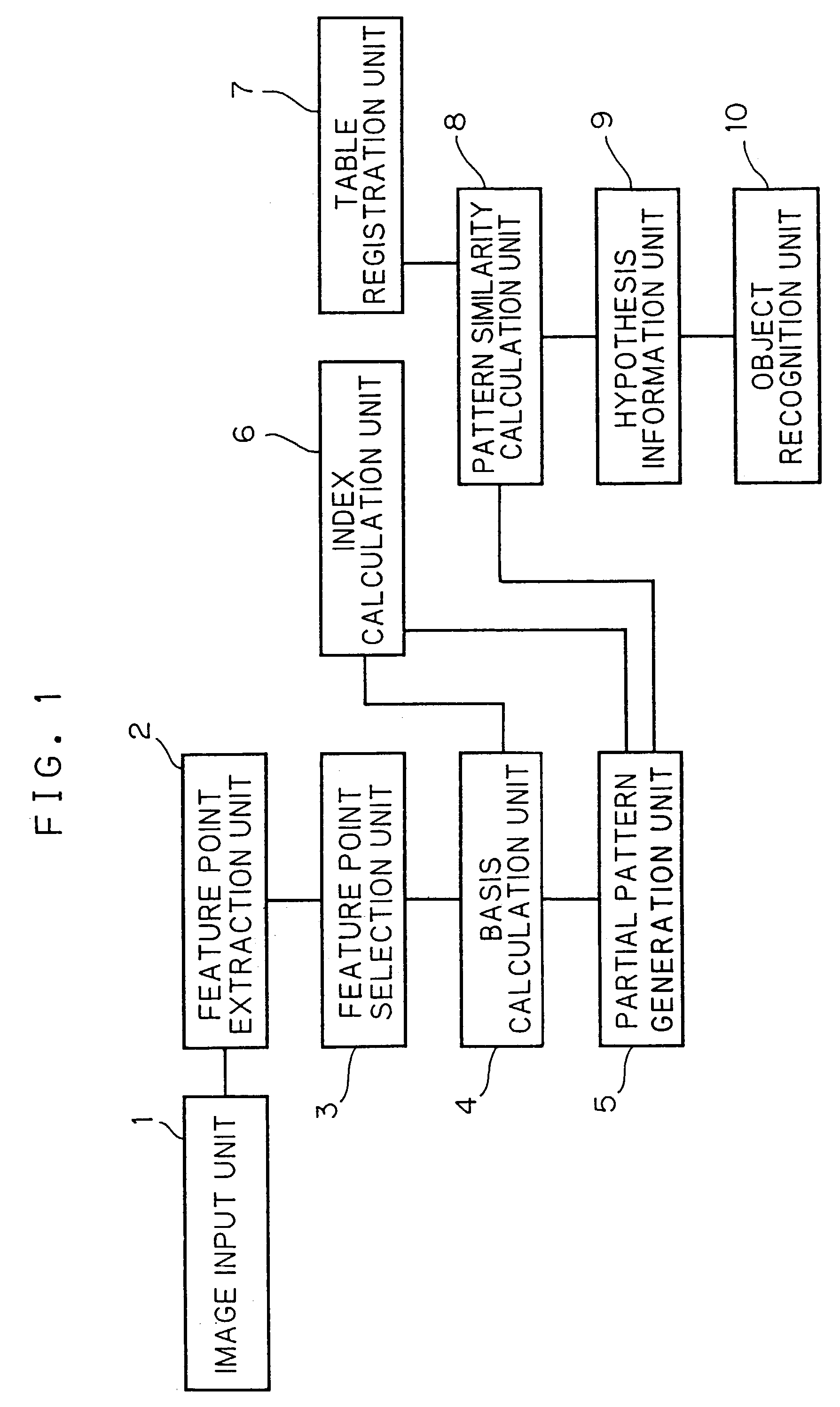
[0035]Hereinafter, a pattern recognition apparatus according to a first embodiment of the present invention will be described with reference to the drawings.

[0036]This embodiment is a method for detecting the position and orientation of an object of interest from a certain image. An object for recognition object may be of any kind. In the present embodiment, a case will be described in which the object is a rectangular-parallelepiped box having a pattern, which is a letter “A” appearing on its one side, as shown in FIG. 4-401.

[0037]In this embodiment, an image obtained by capturing this box at an arbitrary position and an arbitrary orientation is used as one model; and images of the box at various positions and orientations are registered as multiple models.

[0038]Then, which model is similar to a detection object image which captured the same box is judged; and the position and orientation of the box of the detection object image are recognized.

[0039]Thus, the following description ...

Example

Second Embodiment

[0148]A second embodiment will now be described with reference to FIGS. 9 and 10.

[0149]In the second embodiment, a detection method which uses a pattern obtained by taking out an image of a global region in addition to a partial image will be described.

(1) Recognition Method Using Global Image for Face Region Detection

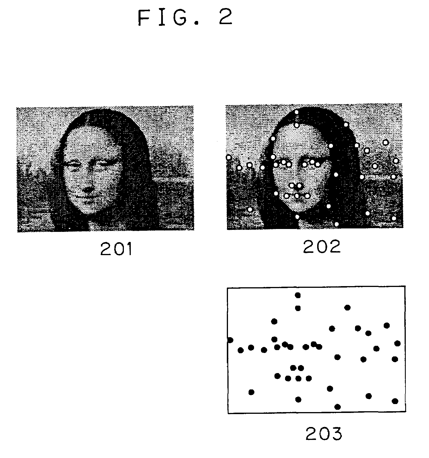
[0150]FIG. 9 shows various data in the recognition method using a global image for face region detection.

[0151]FIG. 9-901 shows an image including a face. Three feature points (nostrils and one lip corner) are selected as interest points; and a rectangle representing a region of a global image (whole face) is shown.

[0152]FIG. 9-902 shows a basis formed by the three points. The angle between vectors and the ratio between the lengths of the vectors are used as indexes of a hash table.

[0153]FIG. 9-903 shows an intensity change pattern on the neighboring region taken out in accordance with the basis formed by the three points.

[0154]In addition, an intensit...

Example

Third Embodiment

[0163]A third embodiment will now be described.

[0164]In the third embodiment, identification of a recognition object is carried out.

[0165]If the orientation of a recognition object is prescribed to a certain extent, it is possible to identify the recognition object based on a model representation approach using a similar hash table.

[0166]For example, as shown in FIG. 11, feature extraction (FIG. 11-1103, 1104) is carried out with respect to an object A (FIG. 11-1101) and an object B (FIG. 11-1102); and partial patterns are taken out based on all the combinations of feature points and registered to a hash table. In this case, the names of the objects are also registered for “Label” in the registration stage (FIG. 11-1105).

[0167]In recognition stage, the foregoing similar procedures are followed and the names of the objects including voted feature points are outputted. Thus, identification of the recognition object is made possible, that is, what object exists can be k...


PUM


Abstract

Pattern recognition apparatus and method for recognizing a recognition object by comparing with pre-registered models. From an inputted image, multiple feature points are extracted; therefrom, combination of multiple feature points is selected; and from the multiple selected feature points, bases which represent the positions and positional relations of these feature points are calculated. A partial pattern of the recognition object corresponding to each of the calculated bases is extracted from the image; and a search place on the table is decided based on an invariant parameter to geometric transformation of the partial pattern. The similarity between the partial pattern of the model registered in the search place on the table and the partial pattern of the recognition object is judged; and a plurality of hypothesis information showing that the recognition object exists in the image is generated based on the similarity between both partial patterns. The identification, position etc are decided based on the information.

Description

BACKGROUND OF THE INVENTION[0001]This invention relates to a pattern recognition method.[0002]A technique for detecting and recognizing the position, orientation and shape of a specific object from an image is important for computer vision. Conventionally, various methods for correctly detecting the position and size of an object from an image with complicated background have been considered (see L. G. Brown, “A Survey of Image Registration Techniques,” ACM Computing Surveys, Vol.24, No.4, pp.325–376).[0003]As a feature-based object detection method among those methods, a geometric hashing method is proposed (see Lamdan, Y. and Wolfson, H. J., “Geometric Hashing: a General and Efficient Model-Based Recognition Scheme,” Proceeding of International Conference Computer Vision, pp.238–249, 1988).[0004]In this geometric hashing method, a geometric object is represented by a set of feature points and a model is described using invariant structural representation for translation, scaling a...

Claims


Application Information

Patent Timeline
IPC IPC(8): G06K9/62G06K9/64
CPCG06K9/6211G06V10/757
Inventor YAMAGUCHI, OSAMU
Owner KK TOSHIBA
Why Eureka
Try Eureka