Remote control system, server-client system, server for controlling terminal device, terminal device operating method, device information sharing method, storage media, and program transmission apparatus

Inactive Publication Date: 2007-04-03
IBM CORP
View PDF16 Cites 74 Cited by
  • Summary
  • Abstract
  • Description
  • Claims
  • Application Information

AI Technical Summary

Benefits of technology

[0009]To resolve the above shortcomings, it is one object of the present invention to eliminate the conventional difficulty encountered when written or oral words must be used in explanations given to describe operations, and to simplify such explanations that are transmitted from remote areas (e.g., by remotely located devices). It is another object of the present invention to share among a plurality of users (e.g., a client and a customer) the operation of a remotely located terminal device, and to share, as a three-dimensional model, the current state of the terminal device and the manip

Problems solved by technology

As the development of techniques for the use of electric home appliances and office equipment has progressed, these terminal devices have tended to become multi-functional and complex.
Therefore, when the only references available are the operating manuals manufacturers usually provide, understanding these complicated terminal devices is a demanding task and ordinary users find them difficult to operate.
As a result, the number of inquiries received by customer support centers is growing rapidly, and an overwhelming load, including the employment of additional workers for their customer support centers, has been imposed on the companies that produce the terminal devices.
In addition to the increase in the number of inquiries, another problem has arisen in that it is very difficult to use written or oral explanations to describe the locations and the manipulation of operating buttons and operating slides on terminal devices, such as electric home appliances.
Even when the electric home appliances are those that are commonly used, it is very difficult to explain to users from remote areas, by phone, the mani

Method used


Image

  • Remote control system, server-client system, server for controlling terminal device, terminal device operating method, device information sharing method, storage media, and program transmission apparatus
  • Remote control system, server-client system, server for controlling terminal device, terminal device operating method, device information sharing method, storage media, and program transmission apparatus
  • Remote control system, server-client system, server for controlling terminal device, terminal device operating method, device information sharing method, storage media, and program transmission apparatus

Examples


Embodiment Construction

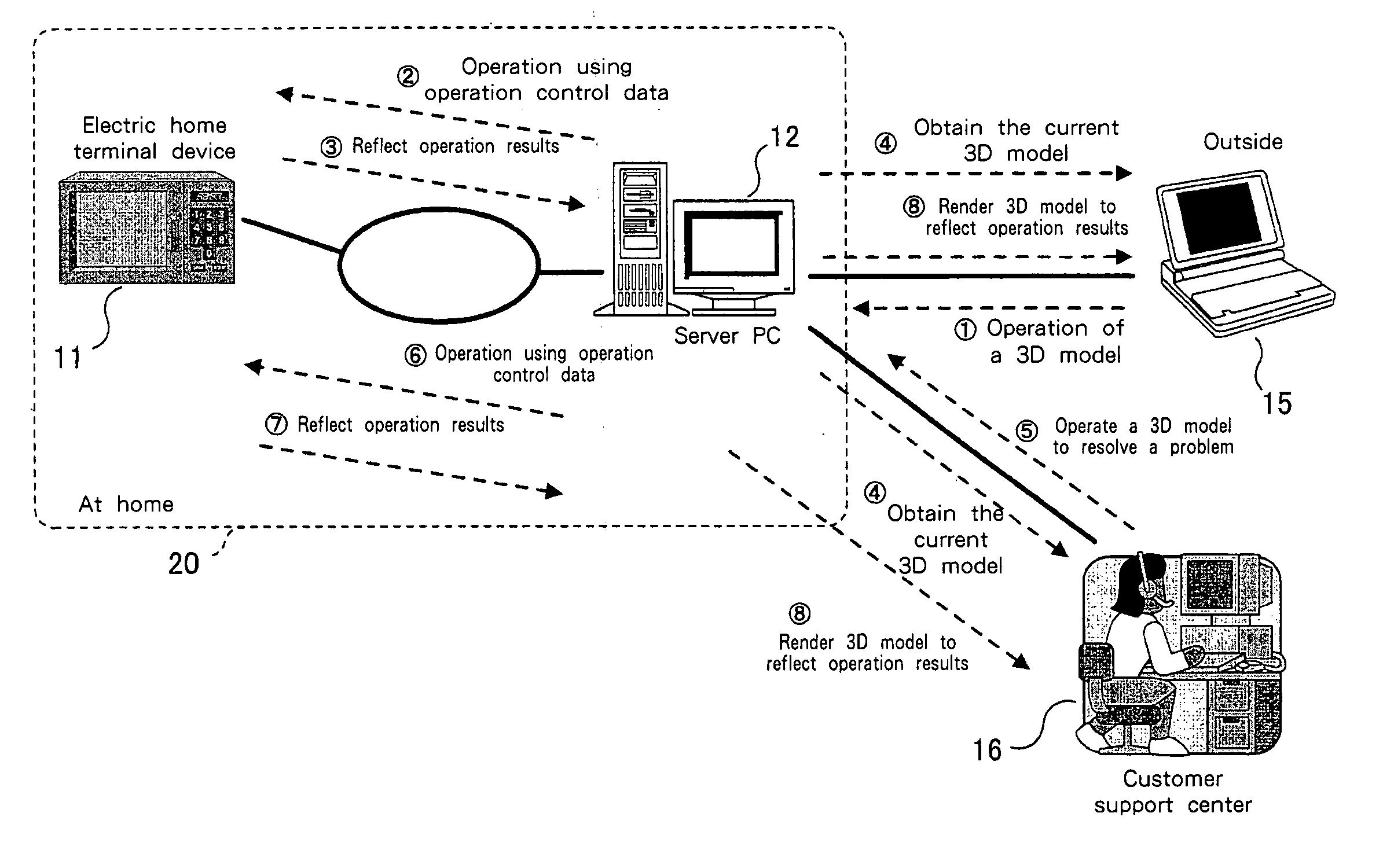
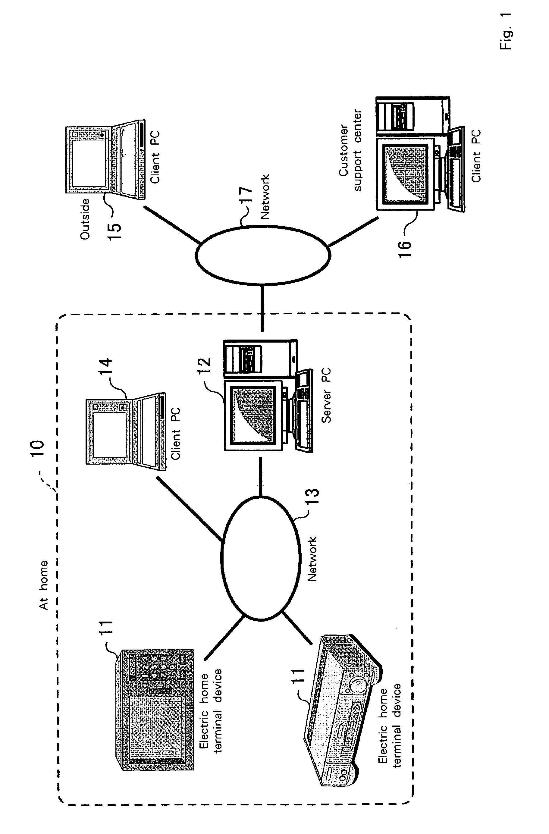
[0065]FIG. 1 is a diagram showing the hardware configuration of a system according to the preferred embodiment. In a home network system 10 in FIG. 1, an electric home terminal device 11, such as an electric home appliance, a server PC 12 and a local client PC 14 are interconnected via an internal network 13, such as an Internet. The server PC 12 is also connected, via an external network 17, such as the Internet, to a remote client PC 15 and a client PC at a customer support center.

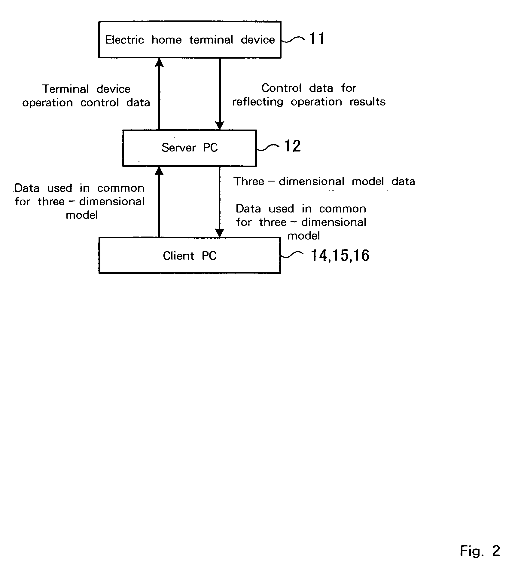
[0066]The electric home terminal device 11 is compatible with Jini, on which the Java VM (Java Virtual Machine) runs, and exchanges control data with the server PC 12. The control data includes data for operating the electric home terminal device 11 and data that reflect the results of an operation. The server PC 12 also exchanges, with the client PCs 14, 15 and 16, data used in common for three-dimensional models.

[0067]FIG. 2 is a schematic diagram showing the transmission of data in the hardware config...


PUM


Abstract

A remote control system includes: an electric home terminal device 11 having a control program; a server PC 12, for transmitting control data to the electric home terminal device 11 and for registering three-dimensional model data concerning the electric home terminal device 11; and client PCs 14, 15 and 16, for receiving the three-dimensional model data from the server PC 12, wherein the client PCs 14, 15 and 16 perform an additional operation upon the receipt of specific three-dimensional model data from the server PC 12, and transmit, to the server PC 12, update data for a three-dimensional model obtained by the additional operation, and wherein the server PC 12 transmits, to the electric home terminal device 11, the control data based on the update data for a three-dimensional model received from the client PCs 14, 15 and 16.

Description

PRIOR FOREIGN APPLICATION[0001]This application claims priority from Japanese patent application number 11-324672, filed Nov. 15, 1999, which is hereby incorporated herein by reference in its entirety.TECHNICAL FIELD[0002]The present invention relates to a remote control system and a terminal device operating method for operating a terminal device, such as an electric home appliance, from a remote area, and for procuring a confirmation for the operation.BACKGROUND ART[0003]As the development of techniques for the use of electric home appliances and office equipment has progressed, these terminal devices have tended to become multi-functional and complex. Therefore, when the only references available are the operating manuals manufacturers usually provide, understanding these complicated terminal devices is a demanding task and ordinary users find them difficult to operate. As a result, the number of inquiries received by customer support centers is growing rapidly, and an overwhelmi...

Claims


Application Information

Patent Timeline
IPC IPC(8): G06F15/16G06F15/173G06F17/50G06F3/00G06F9/44G06F3/14G06F3/048G06F13/00G06T17/00G08C17/00H04Q9/00
CPCG06F3/0482G08C17/00G06F2203/04802G08C2201/41G08C2201/42G08C2201/50
Inventor YOSHIDA, RYO
Owner IBM CORP
Why Eureka
Try Eureka