Elastic Wave Device

Inactive Publication Date: 2011-02-17
HITACHI MEDIA ELECTORONICS CO LTD
View PDF4 Cites 8 Cited by
  • Summary
  • Abstract
  • Description
  • Claims
  • Application Information

AI Technical Summary

Benefits of technology

[0010]Further, a main boundary elastic wave which is excited / resonated in IDT on which the inventors are investigating is a leakage boundary elastic wave, and is provided with an elastic propagation loss. Therefore, in order to achieve a sufficiently high Q value in a boundary elastic wave device, it is necessary to minimize a propagation loss of IDT (maximize an elastic Q value) by optimizing a structure of a boundary elastic wave resonator of a material, a film thickness, a cut angle, and the like.
[0016]It is an object of the present invention to provide a technology which can realize a boundary elastic wave device which has a high quality factor (Q value is equal to or larger than several thousands), and in which k2 falls in a range of 2 through 6%.
[0017]Further, it is another object of the present invention to provide a technology which can easily fabricate a boundary elastic wave device which has a high quality factor (Q value is equal to or larger than several thousands) and in which k2 falls in a range of 2 through 6%.
[0024]A boundary elastic wave device which has a high quality factor (Q value is equal to or larger than several thousands), and in which the k2 falls in a range of 2 through 6% can be realized. Further, a boundary elastic wave device which has a high quality factor (Q value is equal to or larger than several thousands), and in which k2 falls in a range of 2 through 6% can easily be fabricated.

Problems solved by technology

However, although a boundary elastic wave having k2 of 2 through 8% is needed, the boundary elastic wave having k2 of 2 through 8% has not been realized yet.

Method used


Image

  • Elastic Wave Device
  • Elastic Wave Device
  • Elastic Wave Device

Examples


first embodiment

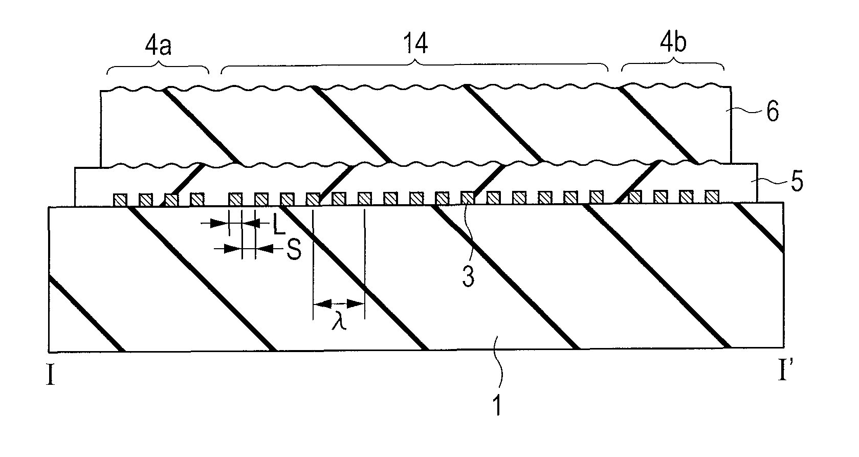
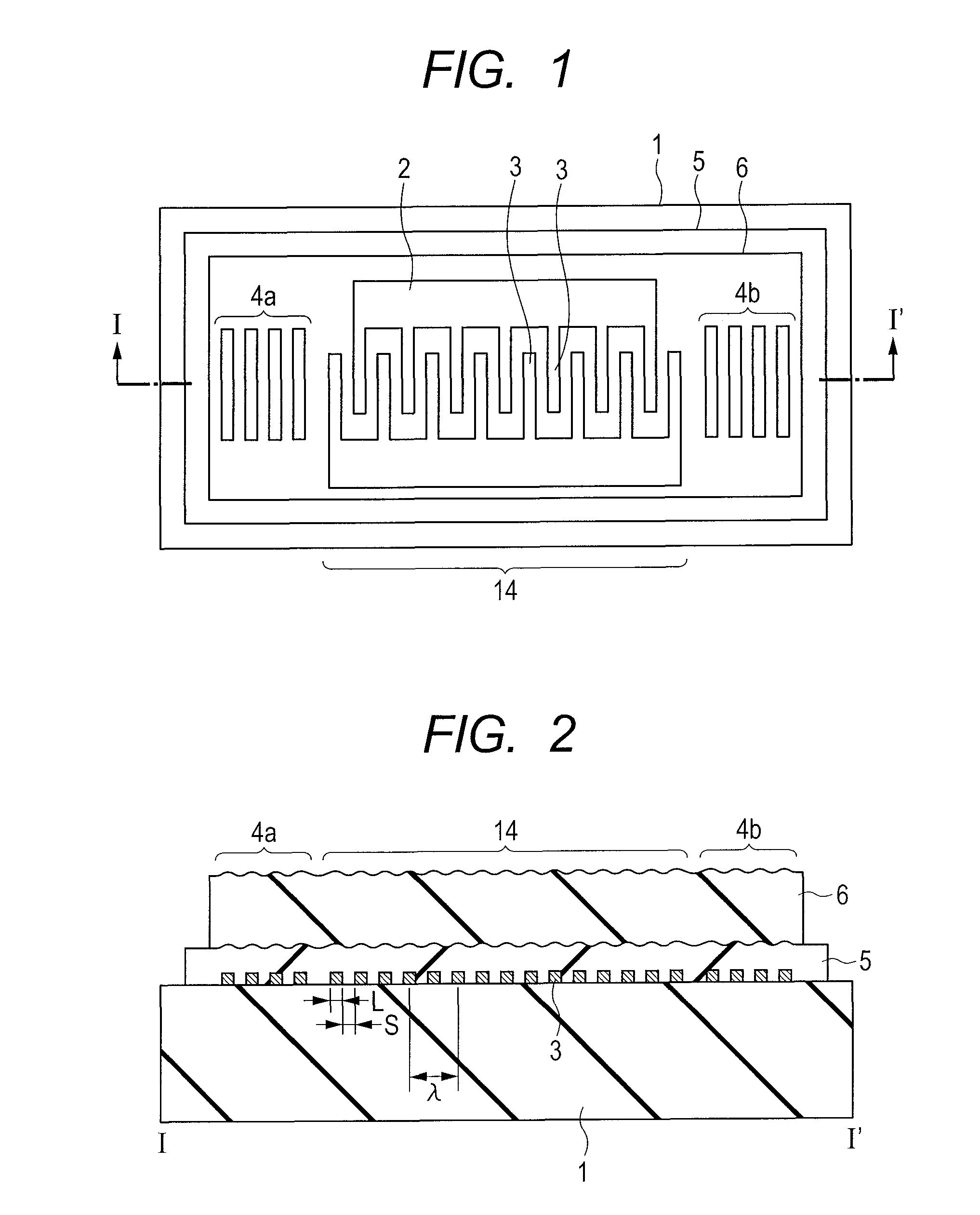
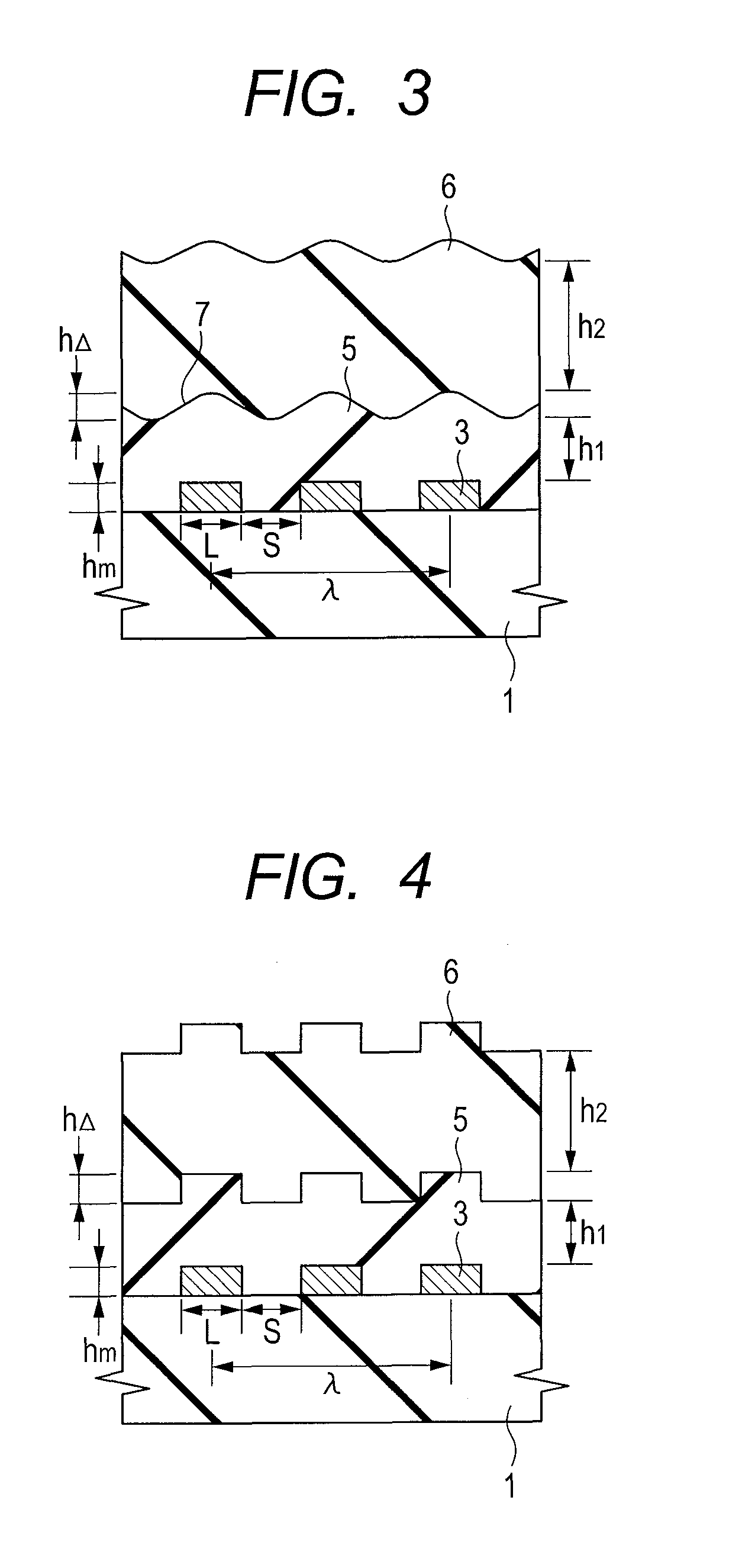
[0053]An explanation will be given of a boundary elastic wave device according to the first embodiment in reference to FIG. 1 through FIG. 12. FIG. 1 is a plane view of an essential portion of a boundary elastic wave resonator, FIG. 2 is a sectional view of an essential portion taken along a line I-I′ of FIG. 1, FIG. 3 is a view for explaining a film thickness of an electrode finger, a film thickness of a silicon oxide film, a film thickness of an aluminum nitride film, an amount of undulations of an interface, a line width of the electrode finger, an interval of the electrode fingers, and a definition of a wave length of the boundary elastic wave excited, FIG. 4 is a model diagram used in analyzing a boundary elastic wave resonator of a 3 media structure, FIGS. 5A and 5B are graph diagrams showing a propagation characteristic of the boundary elastic wave in a case of θ=125°, FIGS. 6A and 6B are graph diagrams showing the propagation characteristic of the boundary elastic wave in a ...

second embodiment

[0078]An explanation will be given of a boundary elastic wave device according to the second embodiment in reference to FIG. 13 through FIG. 23. FIG. 13 is a graph diagram showing a range of h1 / λ and a cut angle θ at which a boundary elastic wave is present. FIG. 14 is a graph diagram showing k2 of a boundary elastic wave in a case of h1 / λ=10%. FIG. 15 is a graph diagram showing k2 of a boundary elastic wave in a case of h1 / λ=20%. FIG. 16 is a graph diagram showing k2 of a boundary elastic wave in a case of h1 / λ=30%. FIG. 17 is a graph diagram showing k2 of a boundary elastic wave in a case of h1 / λ=40%. FIG. 18 is a graph diagram showing k2 of a boundary elastic wave in a case of h1 / λ=50%. FIG. 19 is a graph diagram showing k2 of a boundary elastic wave in a case of h1 / λ=60%. FIG. 20 is a graph diagram showing k2 of a boundary elastic wave in a case of h1 / λ=70%.FIG. 21 is a graph diagram showing k2 of a boundary elastic wave in a case of h1 / λ=80%. FIG. 22 is a graph diagram showing ...


PUM


Abstract

In a boundary elastic wave resonator formed with a cross finger type transducer (IDT) of a wave length λ of a boundary elastic wave, a silicon oxide film, and an aluminum nitride film above a surface of a θYX-LN single-crystal piezoelectric substrate having a predetermined cut angle θ, a film thickness h1 and a cut angle θ or the like of the silicon oxide film are optimized. For example, the film thickness h1 and the cut angle θ are made to be 127.5°≦θ≦129.5° and 20%≦h1 / λ≦100%.

Description

CLAIM OF PRIORITY[0001]The present application claims priority from Japanese patent application JP 2009-188475 filed on Aug. 17, 2009, the content of which is hereby incorporated by reference into this application.FIELD OF THE INVENTION[0002]The present invention relates to an elastic wave device, particularly, relates to a technology which is effective by being applied to a boundary elastic wave device having a piezoelectric substance and a cross-finger type Inter-Digital Transducer (IDT) for a boundary elastic wave, and constituting a solid circuit element of a resonator, a filter or the like of a communication apparatus for a high frequency.BACKGROUND OF THE INVENTION[0003]A boundary elastic wave device is small-sized and is provided with an excellent temperature stability because the boundary elastic wave device can dispense with a hollow package, and because the boundary elastic wave device can use silicon oxide as a temperature compensating film.[0004]For example, in Internati...

Claims


Application Information

Patent Timeline
IPC IPC(8): H01L41/04
CPCH03H9/02559H03H9/0222
Inventor ISOBE, ATSUSHIASAI, KENGO
Owner HITACHI MEDIA ELECTORONICS CO LTD
Why Eureka
Try Eureka