
Compressor control system for vehicle air conditioner

a control system and compressor technology, applied in the direction of domestic cooling equipment, lighting and heating equipment, support, etc., can solve the problem that the engine vehicle cannot be used, and achieve the effect of accurately controlling the rotation speed of the compressor

Inactive Publication Date: 2007-04-10
DENSO CORP
View PDF14 Cites 32 Cited by
  • Summary
  • Abstract
  • Description
  • Claims
  • Application Information

AI Technical Summary

Benefits of technology

The present invention aims to reduce the cost of manufacturing a vehicle by applying an air-conditioning electronic control unit for a compressor driven by an engine to a control system for a compressor driven by an electric motor without a substantial hardware design change. The invention includes a driving electronic control unit that controls the operation of an electric actuator, the drive-power switching of the vehicle, and the charge and discharge of the main battery. The compressor control system also includes a compressor and a compressor electric motor for driving the compressor. The rotation speed of the compressor electric motor is controlled by the driving electronic control unit, which ensures accurate control of the compressor. The invention allows for the direct application of the air-conditioning electronic control unit to the air-conditioning electronic control unit of a hybrid vehicle or an electric vehicle without a substantial hardware design change, reducing the cost of the vehicle. The air-conditioning electronic control unit can communicate with the driving electronic control unit through a local area network of the vehicle.

Problems solved by technology

However, the air-conditioning ECU 107′ for the engine vehicle cannot be used as the air-conditioning ECU 107 for the hybrid vehicle or the electric vehicle without a hardware change.

Method used


Image

  • Compressor control system for vehicle air conditioner
  • Compressor control system for vehicle air conditioner
  • Compressor control system for vehicle air conditioner

Examples


Embodiment Construction

[0028]A preferred embodiment of the present invention will be described hereinafter with reference to the accompanying drawings.

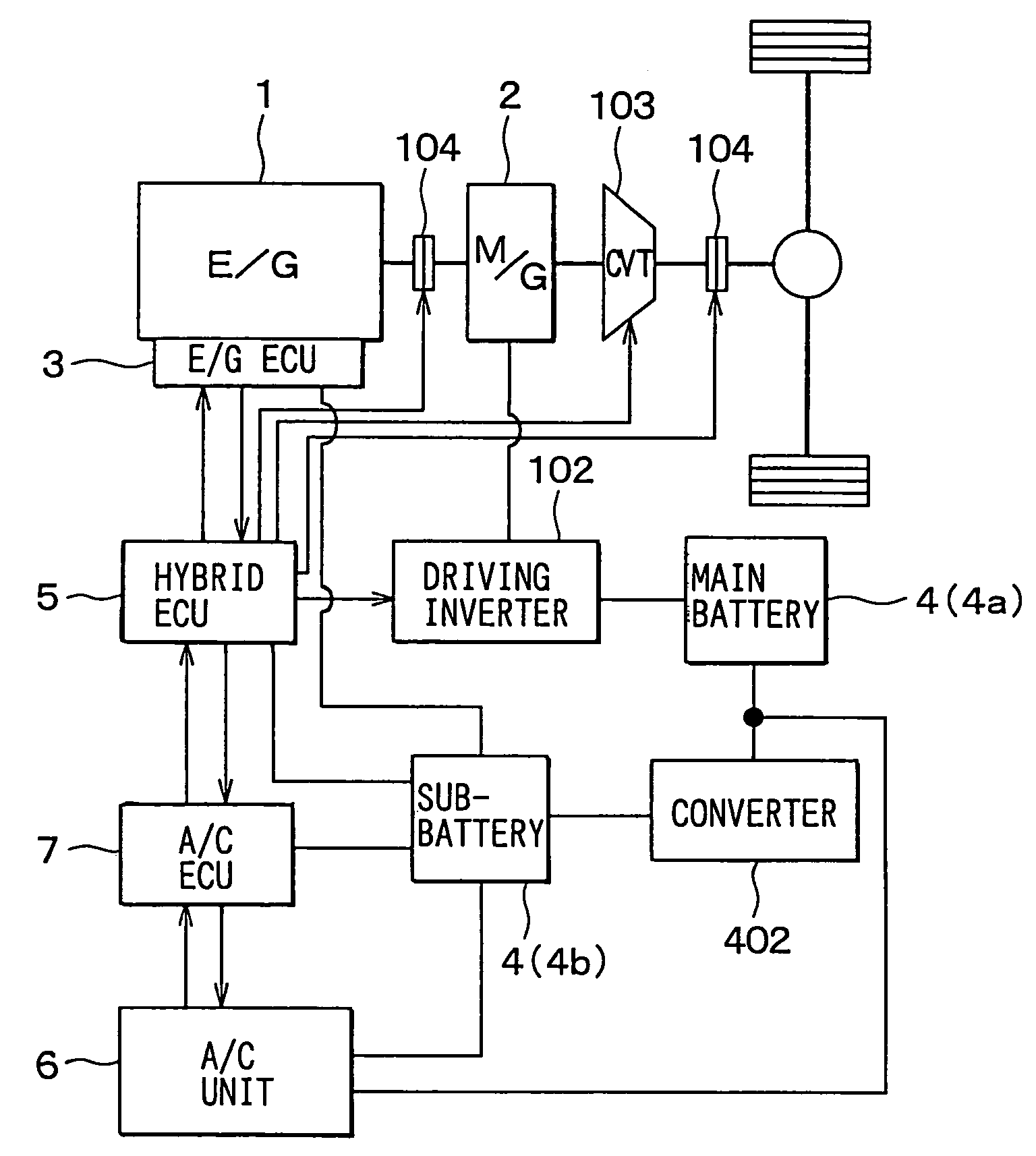
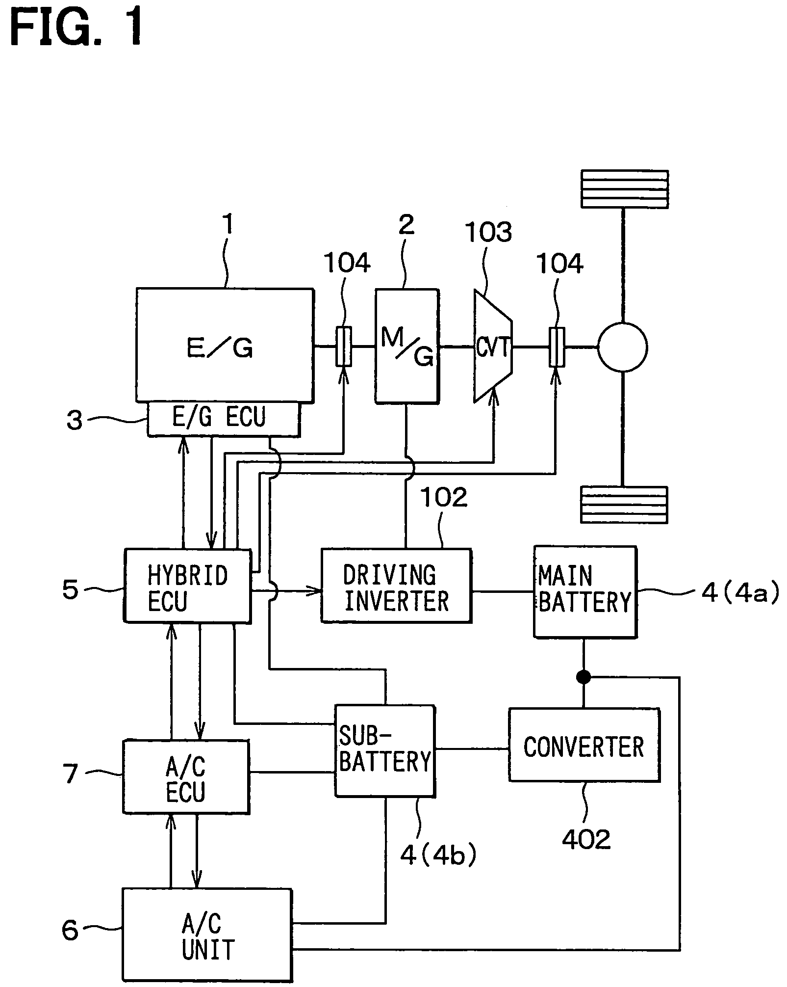
[0029]In this embodiment, a compressor control system of the present invention is typically applied to a hybrid vehicle. As shown in FIG. 1, the hybrid vehicle includes an engine 1, an electric motor generator 2, an engine electronic control unit (ECU) 3, a battery 4 and a hybrid ECU (driving ECU) 5. Here, the engine 1 is an internal combustion system for generating motive power by exploding and burning liquid fuel such as gasoline. The electric motor generator 2 is a motor generator which includes a motor function for an auxiliary driving of the vehicle, and a generator function.

[0030]The engine ECU 3 controls an amount of fuel supplied to the engine 1 and an ignition timing, etc. The battery 4 is a secondary battery which supplies electric power to the electric motor generator 2 and the engine ECU 3, etc. The hybrid ECU 5 performs a control of the electri...


PUM


Abstract

In a compressor control system for a vehicle air conditioner, a hybrid ECU of the vehicle controls a rotation speed of a compressor electric motor. In this case, an output circuit, which outputs a driving signal for driving the compressor electric motor, only needs to be newly provided in the hybrid ECU when a hybrid vehicle or an electric vehicle is manufactured based on an engine vehicle. Therefore, a high cost is not caused even when the output circuit is provided in the hybrid ECU which should be newly designed and manufactured. In addition, because the output circuit does not need to be provided in an air-conditioning ECU which is an existing component of the engine vehicle, the air-conditioning ECU in the engine vehicle can be directly applied to that in the hybrid vehicle without a substantial hardware change. Therefore, design cost can be reduced.

Description

CROSS REFERENCE TO RELATED APPLICATION[0001]This application is based on Japanese Patent Application No. 2003-53709 filed on Feb. 28, 2003, the disclosure of which is incorporated herein by reference.BACKGROUND OF THE INVENTION[0002]1. Field of the Invention[0003]The present invention relates to a compressor control system for a vehicle air conditioner. In the compressor control system, an electric motor for driving a compressor is controlled by a driving electronic control unit that controls a driving of the vehicle.[0004]2. Description of Related Art[0005]In a conventional air conditioner (e.g., JP-A-2000-318435) of a vehicle such as a hybrid vehicle and an electric vehicle, a compressor in a refrigerant cycle system of the air conditioner is driven by an electric motor. Here, the hybrid vehicle is a vehicle which drives while a driving mode is switched between a battery driving mode by an electric motor and an engine driving mode. The electric vehicle is a vehicle which drives on...

Claims


Application Information

Patent Timeline
Patent Type & Authority Patents(United States)
IPC IPC(8): F25D25/00B60H1/22B60H1/00B60H1/32
CPCB60H1/004B60H1/3222B60H2001/3272B60H2001/3292
Inventor HOMAN, TOSHINOBUTAKEO, YUJIOOMURA, MITSUYO
Owner DENSO CORP
Learn More