
Apparatus and method of forming a corrosion resistant coating on a ladder

Active Publication Date: 2007-04-10
TOTAL SEPARATION SOLUTIONS
View PDF16 Cites 18 Cited by
  • Summary
  • Abstract
  • Description
  • Claims
  • Application Information

AI Technical Summary

Benefits of technology

[0015]One significant advantage of the present invention is the ability to expose substantially all surfaces of a ladder structure to a corrosion resistant fluid to enhance the capability of those surfaces to be coated with a layer of the corrosion resistant coating.

Problems solved by technology

Ladders that are employed in firefighting, and especially those aerial ladders that are mounted on vehicles for use in firefighting, are especially vulnerable to corrosion.
The ladders are typically made of steel, and are thus are particularly vulnerable to rusting.
The constant rubbing contact between sections of the aerial ladder, as well as with other firefighting equipment carried by firefighters climbing the ladder, coupled with the frequent exposure to water, often leads to corrosion of the ladder that can seriously compromise the strength of the aerial ladder.
Applying a paint or a galvanizing coating to the exposed surfaces of the ladder has been employed in an attempt to solve the corrosion problem, but the inability to completely cover all portions of the ladder structure, especially around the welds joining the members of the ladder structure, can leave some areas unprotected, and thus does not completely prevent the occurrence of corrosion, and can even lead to faster corrosion at the uncovered areas.
Even if complete coverage is obtained initially, the aforementioned rubbing off (and nicking) of the coating compromises the protection.
More importantly, the interior of the tubular members that form the ladder structure may corrode from moisture that infiltrates the interiors of these elements, and this corrosion is potentially the most dangerous as it can go undetected from visual detection.
In some cases, it is necessary to take the aerial fire trucks out of service so that the integrity of the elements of the aerial ladder can be examined closely and tested, but this involves additional costs and additional downtime for the firefighting vehicle.

Method used


Image

  • Apparatus and method of forming a corrosion resistant coating on a ladder
  • Apparatus and method of forming a corrosion resistant coating on a ladder
  • Apparatus and method of forming a corrosion resistant coating on a ladder

Examples


Embodiment Construction

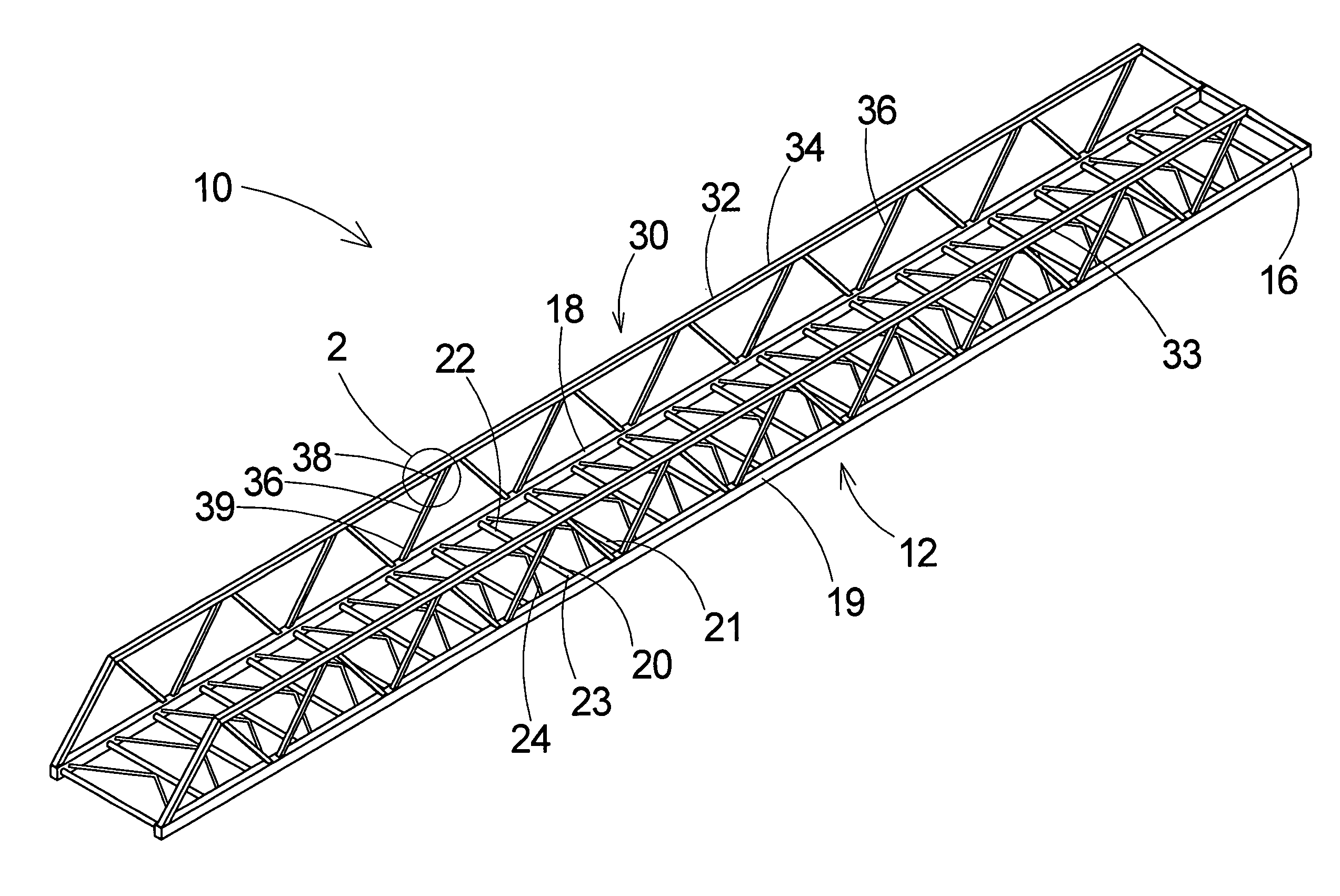
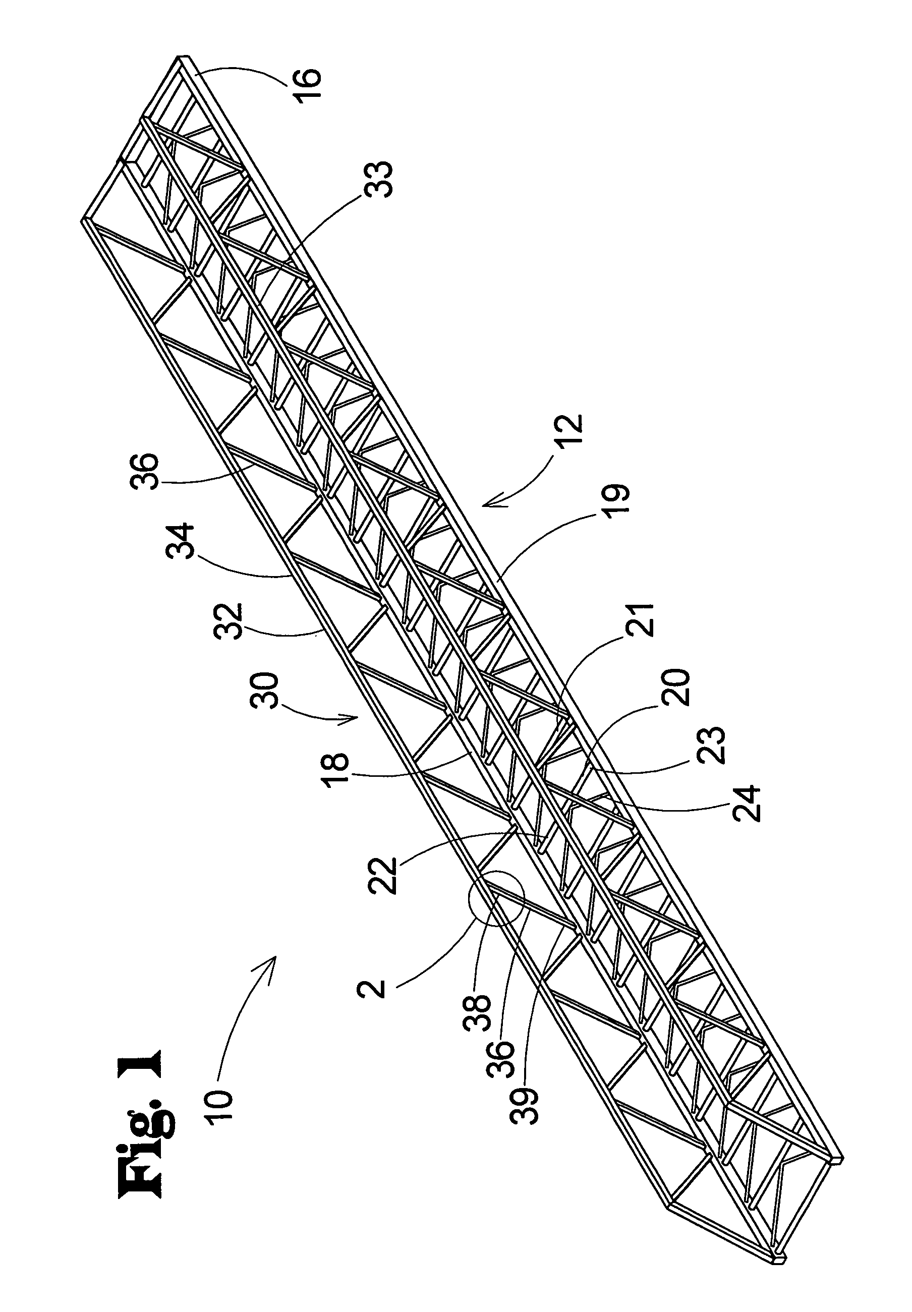
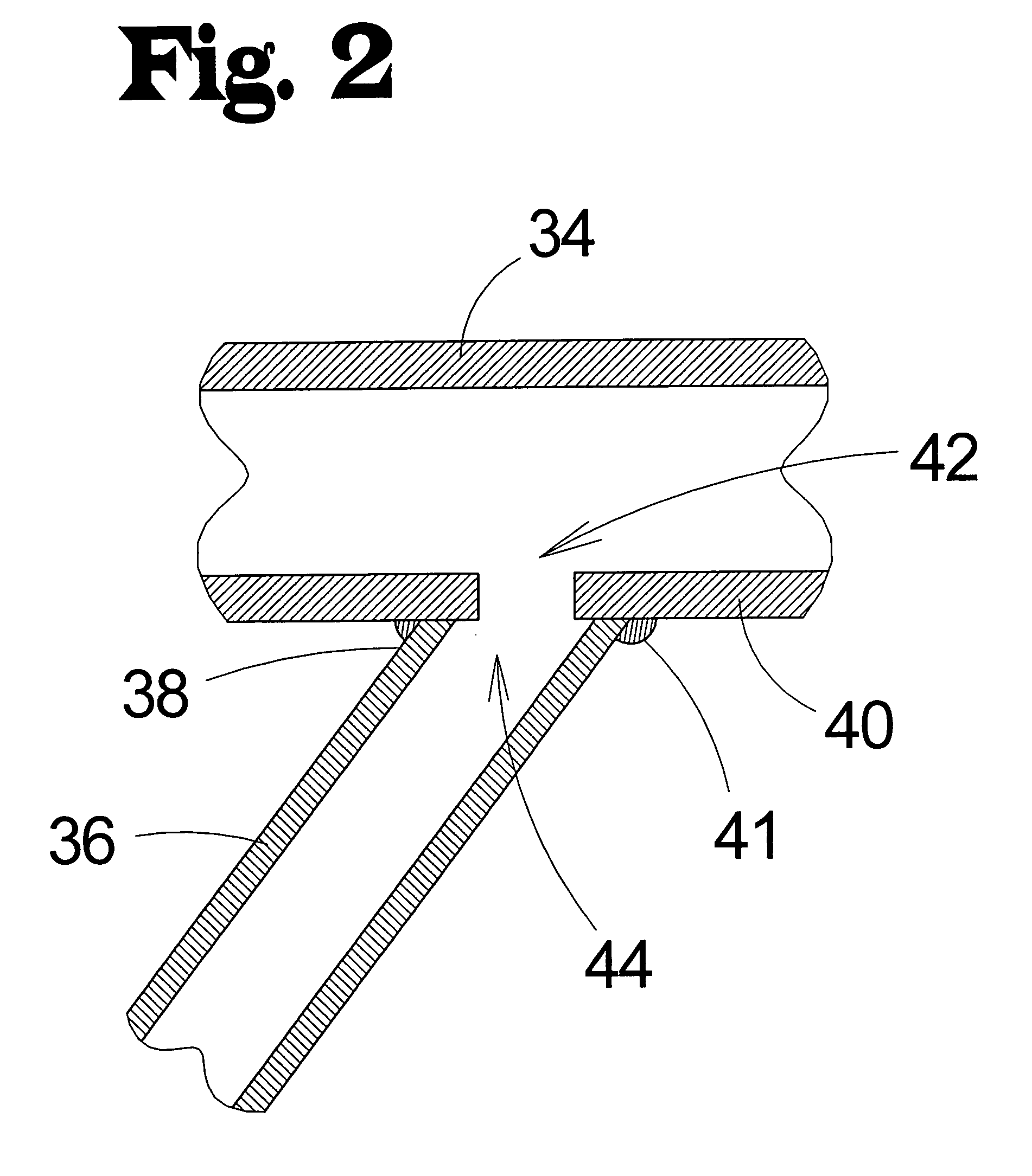
[0022]With reference now to the drawings, and in particular to FIGS. 1 through 4 thereof, a new method of applying corrosion resistant coating for aerial ladders embodying the principles and concepts of the present invention will be described.

[0023]The invention contemplates a ladder structure 10 for a vehicle that exhibits enhanced corrosion resistance, and also a method of forming or fabricating the ladder structure 10 to achieve the enhanced corrosion resistance.

[0024]In the apparatus aspect of the invention, the ladder structure 10 comprises a ladder 12, and a ladder support 30 for enhancing rigidity of the ladder 12 when the ladder is supported at an end in an extended condition (see FIG. 1). The ladder 12 has a first end 14 and a second end 16. The ladder 12 may include a pair of rails 18, 19 that extend between the first 14 and second 15 ends. The ladder 12 may also include a plurality of rungs 20, 21 that extend between the rails 18, 19. Each rung 20, 21 may have opposite en...


PUM

PropertyMeasurementUnit
Corrosion resistanceaaaaaaaaaa

Abstract

A ladder structure for enhancing corrosion resistance is disclosed, which comprises a ladder including a pair of rails and a plurality of rungs extending between and mounted on the rails. At least one of the rails and at least one of the rungs of the ladder comprise substantially tubular elements each having an interior. A pair of the substantially tubular elements of the ladder are connected to each other and the interiors of the connected pair of substantially tubular elements are in fluid communication with each other. Also disclosed is a method of forming the ladder structure with enhanced corrosion resistance.

Description

BACKGROUND OF THE INVENTION[0001]1. Field of the Invention[0002]The present invention relates to methods of treating ladder structures for corrosion resistance and more particularly pertains to a new method of applying a corrosion resistant coating in a manner that is especially useful for aerial ladders and that produces a ladder structure with enhanced corrosion protection that extends over the entire ladder structure.[0003]2. Description of the Prior Art[0004]Ladders that are employed in firefighting, and especially those aerial ladders that are mounted on vehicles for use in firefighting, are especially vulnerable to corrosion. The ladders are typically made of steel, and are thus are particularly vulnerable to rusting. The constant rubbing contact between sections of the aerial ladder, as well as with other firefighting equipment carried by firefighters climbing the ladder, coupled with the frequent exposure to water, often leads to corrosion of the ladder that can seriously co...

Claims


Application Information

Patent Timeline
IPC IPC(8): E06C5/00E06C7/00
CPCC23C2/36C23C2/38E06C5/04E06C7/08E06C7/183
Inventor KREIKEMEIER, ROBERT D.
Owner TOTAL SEPARATION SOLUTIONS
Learn More