Setting apparatus for remote monitoring and controlling system

a technology of remote monitoring and controlling system, applied in the direction of electric controllers, instruments, ignition automatic control, etc., can solve the problems of increasing the size of the coupling portion, the loss of the address setting apparatus, etc., and achieve the effect of reducing the size of the portable uni

Inactive Publication Date: 2007-04-10
MATSUSHITA ELECTRIC WORKS LTD
View PDF8 Cites 4 Cited by
  • Summary
  • Abstract
  • Description
  • Claims
  • Application Information

AI Technical Summary

Benefits of technology

[0014]According to the configuration described above, it is possible to further decrease the size of the portable unit, compared with the case that the portion in which the coupling portion is disposed in the portable unit is different from the battery receiving portion.
[0016]According to the configuration described above, since the base body can be used as a part for fixing the operation device having a size greater than that of the portable unit to the installation surface, it is possible to reduce the whole manufacturing cost for the remote monitoring and controlling system.
[0018]According to the configuration described above, it is possible to decrease the number of components of the stationary unit and to reduce the manufacturing cost, in comparison with the second aspect.

Problems solved by technology

In addition, the address setting apparatus could be easily lost, if a holder or a specific space for holding the address setting apparatus is not additionally prepared.
However, in this method, the size of the portable unit is increased by the size of the coupling portion.

Method used


Image

  • Setting apparatus for remote monitoring and controlling system
  • Setting apparatus for remote monitoring and controlling system
  • Setting apparatus for remote monitoring and controlling system

Examples


Embodiment Construction

[0032]Hereinafter, an exemplary embodiment for carrying out the present invention will be described with reference to the drawings.

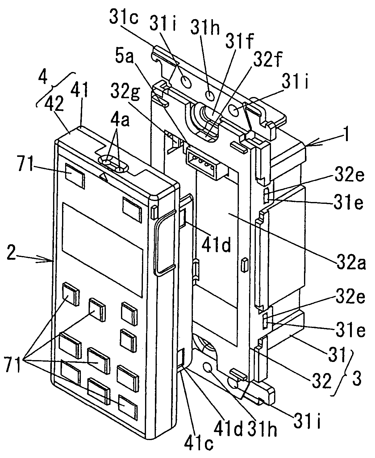
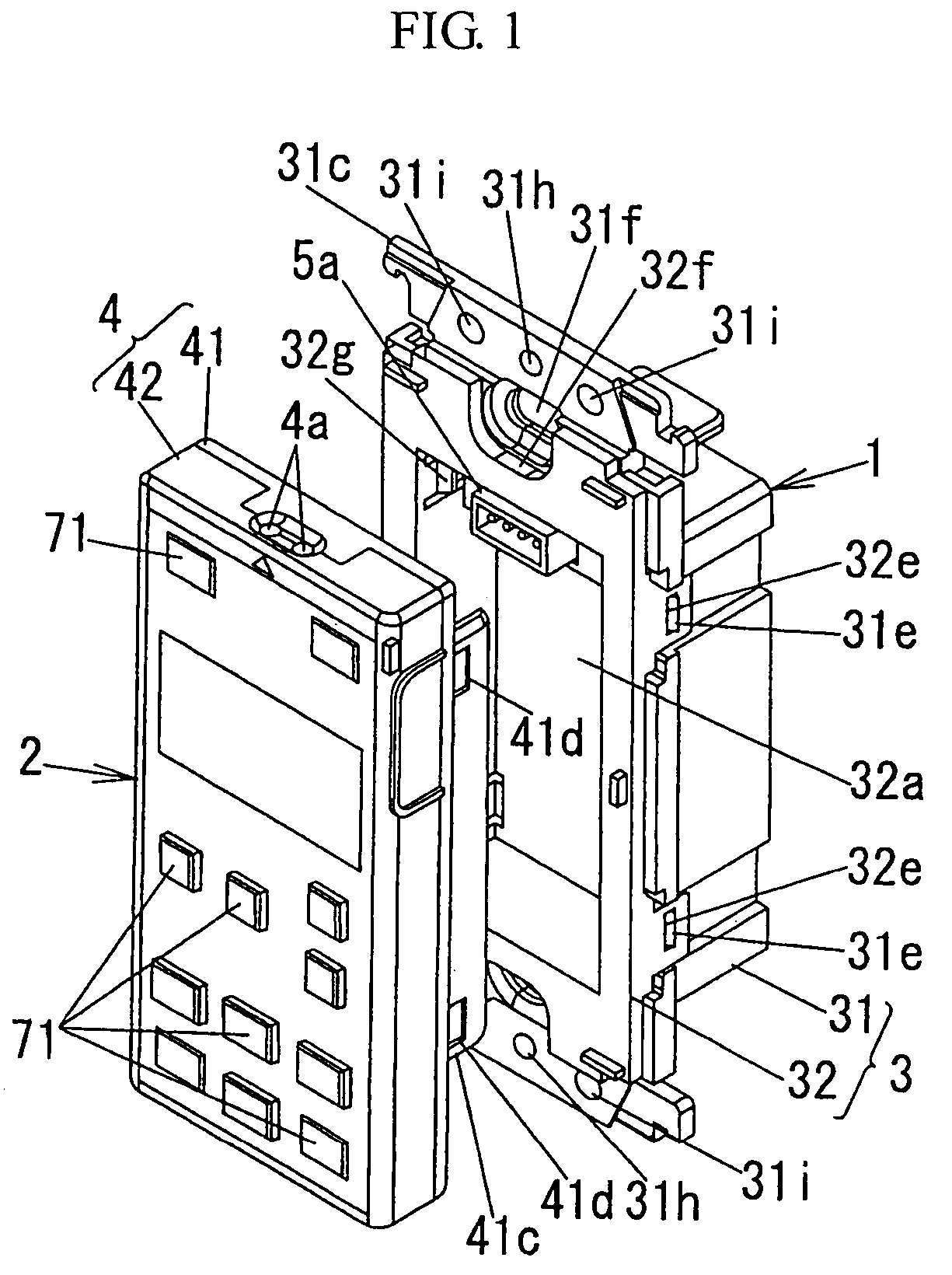
[0033]The exemplary embodiment, as shown in FIG. 1, includes a stationary unit 1 fixed to an installation surface (not shown) and a portable unit 2 detachably attached to the stationary unit 1. In the state that the portable unit 2 is attached to the stationary unit 1, the portable unit 2 is electrically connected to a signal line L (see FIG. 5). Hereinafter, the upward direction and the downward direction are set with reference to FIG. 1, wherein the left-downward and right-upward directions in FIG. 1 are referred to as forward and backward directions and the left-upward and right-downward directions are referred to as left and right directions, respectively.

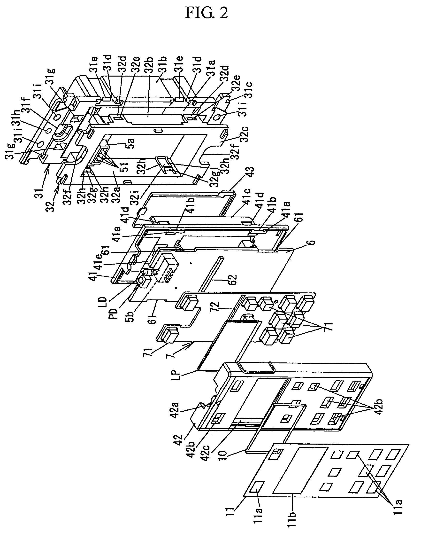
[0034]As shown in FIG. 2, the stationary unit 1 includes a base having a base body 31 which is buried in and fixed to a burial hole (not shown) of the installation surface and a base cover 32 couple...


PUM


Abstract

A setting apparatus for a remote monitoring and controlling system allows a decrease in the size of a portable unit. The setting apparatus includes a stationary unit fixed to an installation surface and a portable unit detachably attached to the stationary unit. A battery receiving portion for receiving a battery is protruded backwardly from the rear surface of the portable unit. By receiving the battery receiving portion of the portable unit in a reception concave portion of the stationary unit and engaging a coupling convex portion with a coupling concave portion of the battery receiving portion, the portable unit is detachably attached to the stationary unit. Since the coupling concave portion for coupling to the stationary unit is formed in the battery receiving portion of the portable unit, the portable unit has a decreased size, compared with a case when the portion coupled to the stationary unit is provided independent of the battery receiving portion.

Description

BACKGROUND[0001]1. Technical Field[0002]The present invention relates to a setting apparatus for a remote monitoring and controlling system.[0003]2. Related Art[0004]Conventionally, there has been provided an address setting apparatus and a pattern setting apparatus for a remote monitoring and controlling system comprising an operation device having switches in which a specific address is set for each switch, a control device connected with loads in which a specific address is set for each load, and a transmission controller transmitting and receiving a transmission signal between the operation device and the control device through a signal line to which the operation device and the control device are branched, in manner of a time division multiple transmission, generating control data for controlling the loads based on monitoring data received from the operation device when the switches are operated, and transmitting the control data to the control device connected with the loads a...

Claims


Application Information

Patent Timeline
Patent Type & Authority Patents(United States)
IPC IPC(8): G06F17/00G06F7/00G06K7/10
CPCG08C17/02G08C15/06G08C2200/00
Inventor KAWAMATA, MOTOSUGU
Owner MATSUSHITA ELECTRIC WORKS LTD
Why Eureka
Try Eureka