
Framed storm drain insert sediment filter

a sediment filter and storm drain technology, applied in the field of storm water sewer systems, can solve the problems of clogging the outflow of storm basins, affecting the free flow of water through the filter, so as to achieve the effect of easy removal from the basin

Active Publication Date: 2007-04-10
METROCHEM
View PDF21 Cites 40 Cited by
  • Summary
  • Abstract
  • Description
  • Claims
  • Application Information

AI Technical Summary

Benefits of technology

[0008]The advantages of the new design is that it is inexpensive and can be easily removed from the basin without fear of collapse into the basin due to the structural frame sitting on top of the basin recesses.
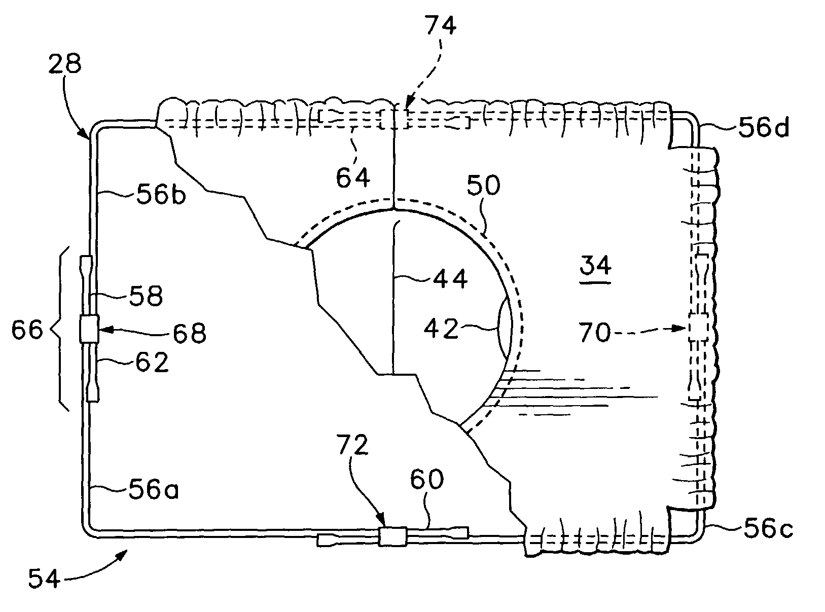
[0009]An alternate design uses the same collar and filter bag. The wire frame, however, is formed from four L-shaped wires that each overlap and form the four corners of the frame. The overlapping portions are slidingly clamped together with a heavy-duty “staple” of a type currently used within the furniture industry. The overlapping wires can then slide relative to one-another so that the dimensions of the rectangular frame can be changed and fitted into differently sized drain basins. The rectangular collar material is “gathered” along the wire frame so that its dimensions can change as well.

Problems solved by technology

Several treatment problems have been identified: stormwater run-off is contaminated with heavy metals and hydrocarbons which have leaked onto the streets and highways from a variety of sources, and leaves and other debris enter through the storm drain grate and clog storm basins outflows.
Over time, the solids built up on the filter, thereby impeding the free flow of water through the filter.
As a result, the collected water flooded the area surrounding the storm sewer.
These designs, while an improvement over the above-ground filters, suffer from several drawbacks.
When the grate is lifted, however, the bag is subject to slide into the catch basin.
The remaining prior art uses rigid frames that are adapted to fit a specifically sized drain opening and were thus not easily adaptable to differently sized or shaped openings.

Method used


Image

  • Framed storm drain insert sediment filter
  • Framed storm drain insert sediment filter
  • Framed storm drain insert sediment filter

Examples


Embodiment Construction

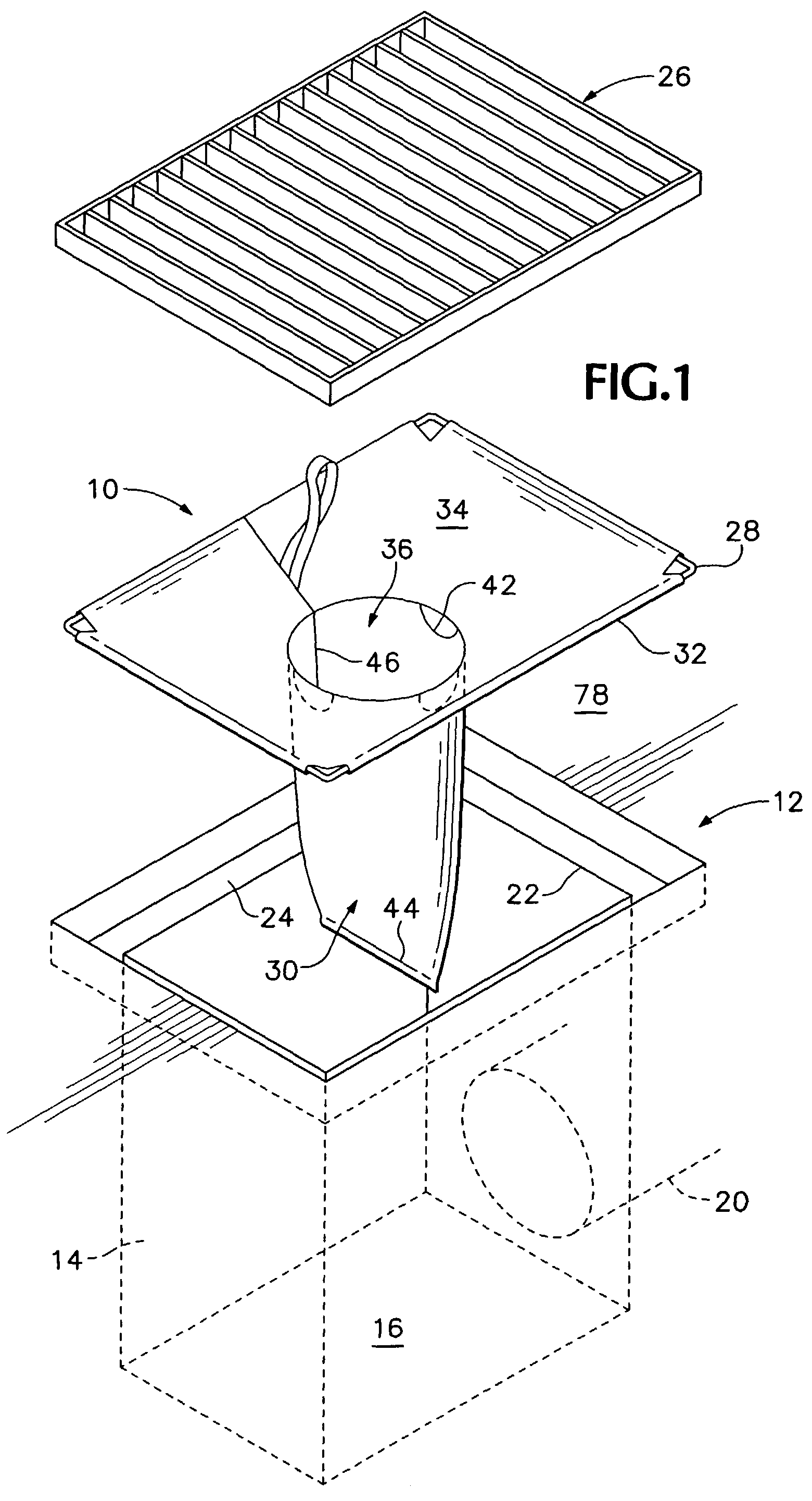
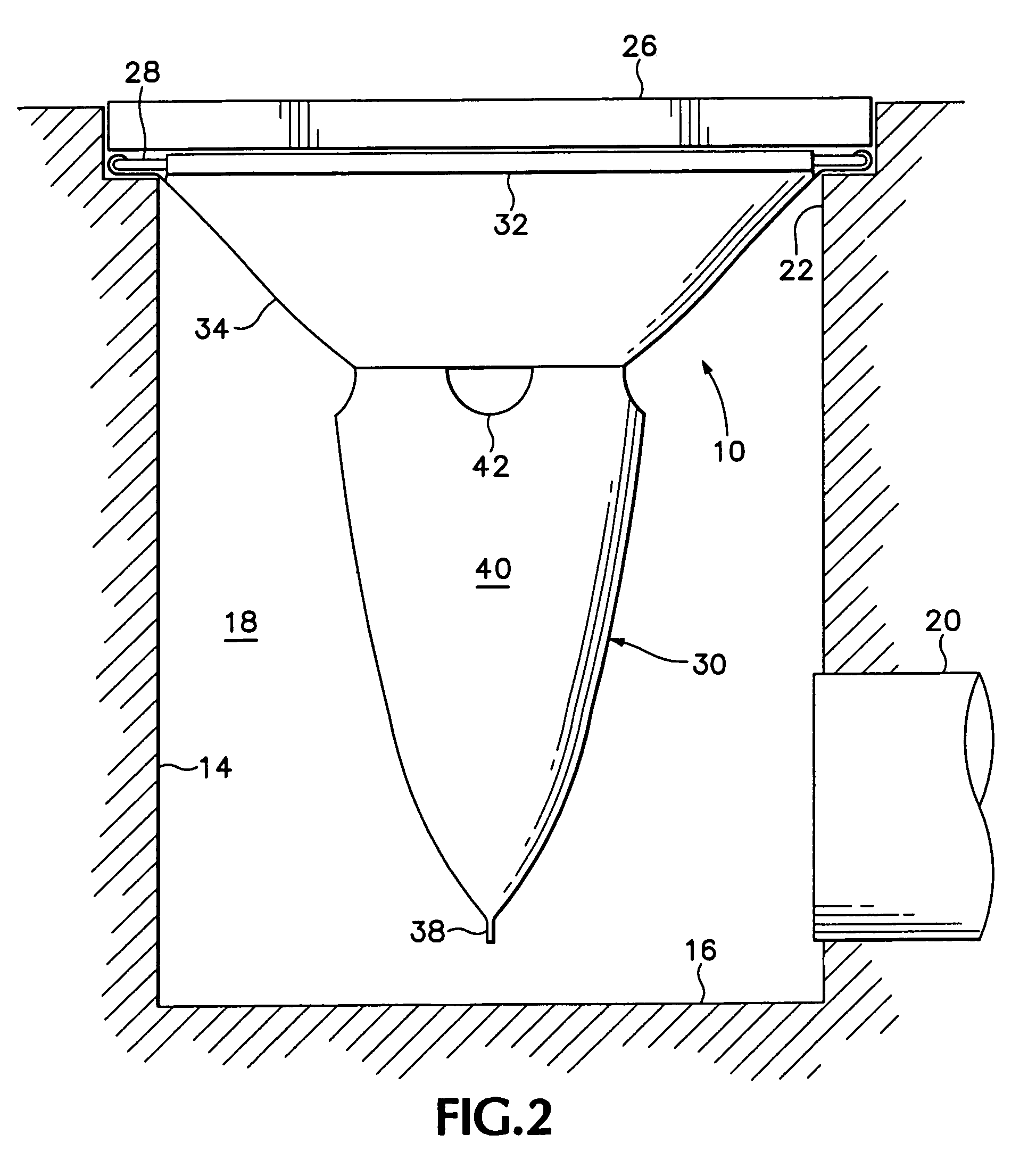
[0021]A catch basin filter constructed according to a preferred embodiment of the invention is shown generally at 10 in FIG. 1. Filter 10 is intended to be installed within a below-grade 78 catch basin 12 of a type having basin sidewalls 14 and floor 16 defining a chamber 18. A sewer pipe 20 extends away from one of the sidewalls 14 a distance above the floor 16. There would typically be four sidewalls for a rectangular chamber and one continuous sidewall for a cylindrical chamber. The catch basin 12 includes an upper end defining a catch basin inlet 22 and a recess 24 located at the upper end into which a grate 26 is normally received. Ground water and solids flow through the grate and inlet, into the catch basin chamber 18, and thence out through the sewer pipe 20.

[0022]As shown also in FIGS. 2 and 3, catch basin filter 10 includes a two-dimensional support frame 28 adapted to be received within and rest upon recess 24 of catch basin 12 and beneath grate 26. As the catch basin inl...


PUM

PropertyMeasurementUnit
Dimensionaaaaaaaaaa

Abstract

The new design has three primary features: (1) a rectangular collar having a centrally located circular cutout with sewn loops formed on the outer edges of the collar; (2) a filter bag having top edges attached to the rectangular collar along the periphery of the circular cutout so that the bag is inserted within the cutout and drops below the level of the collar; and (3) a heavy gauge steel wire inserted within the sewn loops of the rectangular collar forming a structural frame along the periphery of the rectangular collar. The structural frame is preferably formed with overlapping portions coupled together with a retaining means. The overlapping portions are slidably moved relative to one another to change the first and / or second dimension of the frame so that the filter can fit within catch basins openings of various measurements.

Description

BACKGROUND OF THE INVENTION[0001]This invention relates generally to storm water sewer systems, and more particularly to a drain insert adapted to prevent sediment or debris such as leaves, sand, stones, gravel and, in some cases, petroleum products, from entering into the storm water removal system.[0002]There is increased importance being placed by cities on water treatment prior to the water entering the storm sewer system. Several treatment problems have been identified: stormwater run-off is contaminated with heavy metals and hydrocarbons which have leaked onto the streets and highways from a variety of sources, and leaves and other debris enter through the storm drain grate and clog storm basins outflows. In a typical storm water collection system, ground water from heavy rains or melted snow is collected in a storm sewer catch basin and flows into an underground sewer line. The water flows into the basin through openings in a grate on the top of the basin.[0003]Water entering...

Claims


Application Information

Patent Timeline
IPC IPC(8): B01D29/27E03F1/00
CPCB01D29/27E03F1/00E03F5/0404
Inventor SASAKI, DEREK A.SASAKI, RONI R.
Owner METROCHEM
Learn More