
Projection exposure machine comprising a projection lens

a technology of projection lens and projection lens, which is applied in the direction of photomechanical equipment, instruments, printers, etc., can solve the problems of large absolute value of spherical aberration, spherical aberration, and inability to tolerate large spherical aberration, and achieve good quality

Inactive Publication Date: 2007-04-10
CARL ZEISS SMT GMBH
View PDF19 Cites 23 Cited by
  • Summary
  • Abstract
  • Description
  • Claims
  • Application Information

AI Technical Summary

Benefits of technology

The present invention provides a projection lens with a high quality, in particular with a low aperture, that has fewer lenses and can correct field curvature. The lens has a specific shape and thickness that minimizes image errors caused by the lens. The invention also provides a manipulation chamber for correcting field curvature in the lens. The use of an aspheric optical element in the first lens group and the arrangement of optical elements in the sixth lens group with specified radii of curvature and diameter / thickness ratios can help achieve better image quality and efficiency in correcting astigmatism and telecentricity. The invention also allows for a very small thick end plate in the output side of the lens. The aspheric and the arrangement of optical elements in the first lens group can help predict and correct astigmatism and telecentricity in the lens. The invention provides a manipulation chamber that can be used as a manipulable gas interspace in a projection lens. The refractive power of the optical elements in the sixth lens group can be varied by changing the gas mixture or pressure. The invention also provides a method for tuning the projection lens by manipulating the gas mixture or pressure in the manipulation chamber.

Problems solved by technology

In the case of lithographic lenses, spherical aberration, inter alia, arises as image error owing to environmental influences, such as change in air pressure, for example.
Other parameters are lens heating and compaction, which likewise lead to spherical aberration.
Particularly in the case of a high numerical aperture, the absolute value of the spherical aberration becomes very large and no longer tolerable given the required accuracies.
However, for 365 nm, 193 nm lenses this method no longer functions and specifically the chromatic correction of the lenses, that is to say the use of different materials, causes the different variation in the refractive indices with the wavelength to lead to image errors which cannot be tolerated.
However, it is disadvantageous of this method that in addition to the large outlay required therefore other errors are once again introduced thereby as well.
It is therefore common to all known methods that they more or less effectively compensate spherical aberration but at the same time once again introduce other errors, or act only incompletely.

Method used


Image

  • Projection exposure machine comprising a projection lens
  • Projection exposure machine comprising a projection lens
  • Projection exposure machine comprising a projection lens

Examples


Embodiment Construction

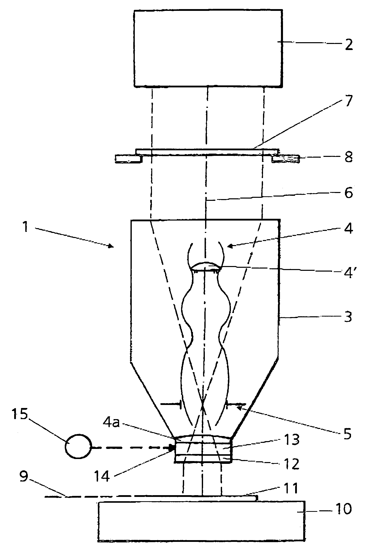
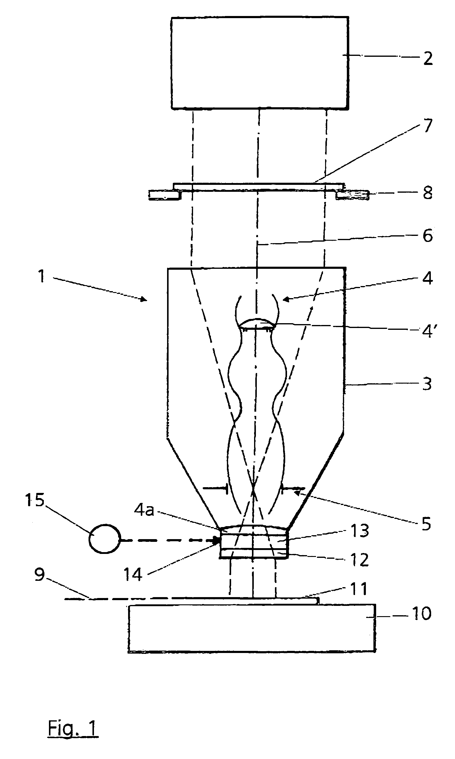
[0036]The principle of the design of a projection exposure machine 1 is described below with the aid of FIG. 1. The projection exposure machine 1 has an illuminating device 2 and a projection lens 3. The projection lens 3 comprises a lens arrangement 4 with a multiplicity of lenses 4′ (not illustrated in more detail in FIG. 1) and an aperture stop 5. The lenses 4′ are arranged along an optical axis 6. A mask or reticle 7, which is held in the beam path by means of a mask holder 8, is arranged between the illuminating device 2 and the projection lens 3. The mask 7 is imaged on an image plane 9 by means of the projection lens 3 by a clearly reduced factor. Such masks 7 used in microlithography have a micrometer or nanometer structure which is imaged on the image plane 13 by means of the projection lens 3 in a fashion reduced in size down to a factor of 10, in particular the factor 4. The minimum structures which can still be resolved depend on the wavelength λ of the light used for th...


PUM

PropertyMeasurementUnit
radiiaaaaaaaaaa
refractive indexaaaaaaaaaa
wavelengthaaaaaaaaaa

Abstract

A projection exposure machine comprises a projection lens with a lens arrangement and at least one stop. The lens arrangement comprises a group of optical elements which is arranged between the stop and the image plane. An optical element of the group situated close to the image plane has a thickness of at least 6.5% of the entire stop diameter.

Description

[0001]This application is a CIP of Ser. No. 09 / 847,658 May 2, 2001 U.S. Pat. No. 6,867,923.BACKGROUND OF THE INVENTION[0002]1. Field of the Invention[0003]The invention relates to a projection exposure machine in microlithography comprising a projection lens with a lens arrangement. The invention also relates to a manipulation chamber for correcting field curvature and a method for tuning projection lenses.[0004]Reference is made to U.S. Pat. No. 4,871,237, U.S. Pat. No. 4,676,614 and U.S. Pat. No. 5,559,584 for details on the general prior art.[0005]2. Description of the Related Art[0006]In the case of lithographic lenses, spherical aberration, inter alia, arises as image error owing to environmental influences, such as change in air pressure, for example. Other parameters are lens heating and compaction, which likewise lead to spherical aberration. Particularly in the case of a high numerical aperture, the absolute value of the spherical aberration becomes very large and no longer...

Claims


Application Information

Patent Timeline
Patent Type & Authority Patents(United States)
IPC IPC(8): G02B9/00G02B3/08G03B27/54G02B3/14G02B13/14G02B13/18G02B17/08G03F7/20
CPCG02B3/14G02B13/143G02B13/18G03F7/70225G03F7/70241G03F7/70883G03F7/70933
Inventor SCHUSTER, KARL-HEINZ
Owner CARL ZEISS SMT GMBH
Learn More