Removable filter holder and method

a filter holder and removable technology, applied in the field of cooling devices, can solve the problems of inability to remove the filter holder, contamination of the x-ray tube surface, etc., and achieve the effect of convenient visual inspection, easy and straightforward detachment operation, and easy reattachmen

Active Publication Date: 2007-04-10
PROTO MANUFACTURING LTD
View PDF4 Cites 10 Cited by
  • Summary
  • Abstract
  • Description
  • Claims
  • Application Information

AI Technical Summary

Benefits of technology

[0008]The present detachable filter carrier is advantageous in that it obviates the need to disassemble the cooling system for the X-ray head assembly or goniometer to service the cooling fluid filter, such as for cleaning or replacement thereof, as required with prior X-ray goniometer heads where the cooling head or manifold was fastened to the X-ray tube so that accessing filters that may be provided in the cooling head necessitated removal of the tube along with the cooling head from the outer housing therefor. In the present invention, a detachable connection between the filter carrier or holder and X-ray head is provided so that with a relatively easy and straightforward detachment operation, the carrier can be removed from the X-ray head leaving the X-ray head tube and housing therefor substantially intact assembled together. In this manner, after servicing of the filter, the carrier can be easily reattached to the X-ray head without concern for proper alignment and orientation of the tube and housing, and particularly the tube anode assembly and housing window, as is necessary with the previously described cooling system. The detachable connection is preferably a threaded connection such as between the body of the filter carrier itself and the X-ray head or more particularly a cooling head for being secured thereto. Other detachable connections are also contemplated such as bayonet connections, friction fits, and the like.
[0009]In a preferred form, the present invention provides coolant flow paths within the walls of the outer housing and includes a filtration site which is accessible from outside of the outer housing. In one arrangement, the present invention provides filter screens carried on a removable carrier or holder which is installed and removed from outside the outer housing without requiring disassembly of the X-ray tube from the outer housing or other components of the X-ray generating device. Accordingly, the filtration device can be serviced without disturbing the X-ray tube, and in particular, without requiring the X-ray tube to be removed or its surfaces contacted by service personnel. In one aspect, a removable fluid directing assembly is provided for being removably mounted to the cooling head adjacent the anode region of the X-ray tube with the cooling head installed on the x-ray head. Accordingly, with the fluid directing assembly removed, a limited visual inspection of the X-ray tube and specifically the otherwise obstructed anode surface can be performed without disassembly of the outer housing and tube or other components of the X-ray device as previously required. In this manner, the anode assembly can be more easily visually inspected for any potential damage thereto as by overheating by simply removing the fluid directing assembly from the cooling head.
[0010]In one aspect, the present invention provides a cooling system for an X-ray diffraction tube in which a housing in the form of a hollow cylindrical jacket surrounds at least a portion of the X-ray diffraction tube, with the hollow interior of the jacket including a flow channel for channeling flow of a liquid coolant. The housing further includes a receptacle for receiving a filter holder so as to dispose a filter in the flow channel to thereby provide cleaning of the liquid coolant. In one preferred embodiment, the housing comprises a cylindrical hollow jacket surrounding the X-ray diffraction tube with the hollow interior of the jacket comprising the flow channel. A cooling head engageable with one end of the cylindrical hollow jacket defines an internal flow passageway in communication with the flow channel of the hollow jacket. A receptacle is located in the center of the cooling head with internal passageways within the cooling head extending in radial directions so as to bring flow of coolant into and out of the receptacle. The filter holder is provided in the form of a bolt or screw fastener having an enlarged head and a hollow body or stem portion receiving a filter screen. A cross hole extending through the stem provides flow communication with the hollow stem, permitting coolant flow across the surface of the filter screen. The filter holder is threadingly engaged with the cooling head receptacle portion, thereby allowing the filter holder to be quickly and easily removed from the device, as desired. The filter holder in this embodiment contacts only the cooling head portion of the outer housing and requires neither disassembly of the X-ray head for removing the holder or contact with the X-ray tube. With the filter holder removed from the cooling head, the filter screen can be removed, washed or replaced with a fresh filter screen.
[0011]In other aspects, the present invention can be incorporated in X-ray generating devices in which the space between the X-ray tube and outer housing is filled with a coolant fluid, either gas or liquid. Coolant flow is conducted through the outer housing to a receptacle portion of the cooling head, as described above. A removable filter holder engaged with the receptacle portion carries a filtration member such as a filter screen to provide continual cleaning of the coolant while coolant flow conditions are maintained.

Problems solved by technology

It is important that the particulates and other contaminants be removed from the coolant medium before they enter regions of high electric field between the inner and outer housings, thus giving rise to the possibility of a high voltage breakdown event.
Such filtration service procedures create difficulties and can compromise the alignment of the tube relative to the housing, and particularly the tube anode assembly relative to the housing window, and may lead to contamination of the X-ray tube surfaces.
With respect to tube / housing alignment, it has been found that unbolting the tube and housing from each other for disassembly and then rebolting the tube and housing together can cause slight variations in the relative positions between the anode assembly and window due to the tolerances between the bolts and apertures therefor potentially leading to inaccuracies in test measurements.

Method used


Image

  • Removable filter holder and method
  • Removable filter holder and method
  • Removable filter holder and method

Examples


Embodiment Construction

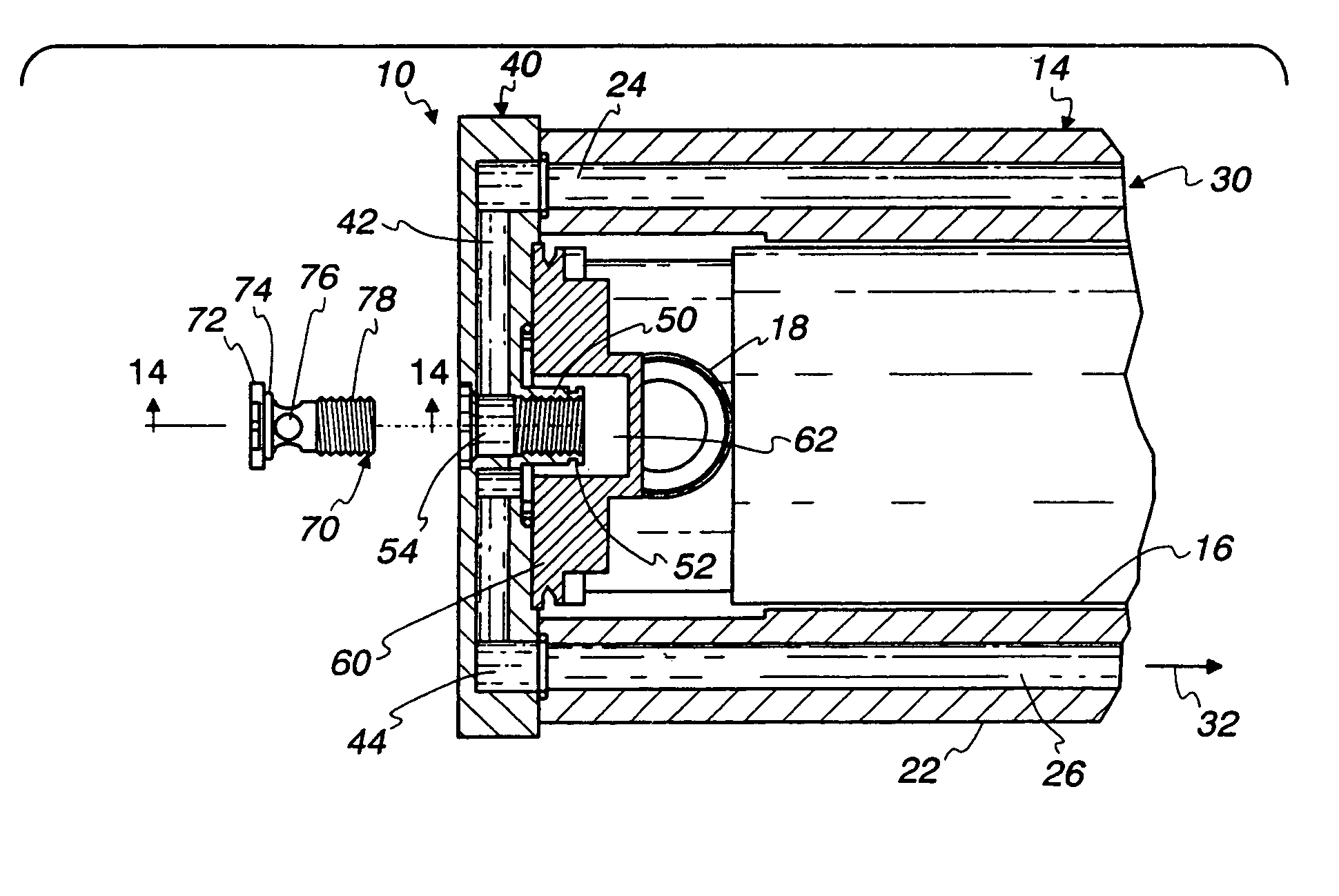
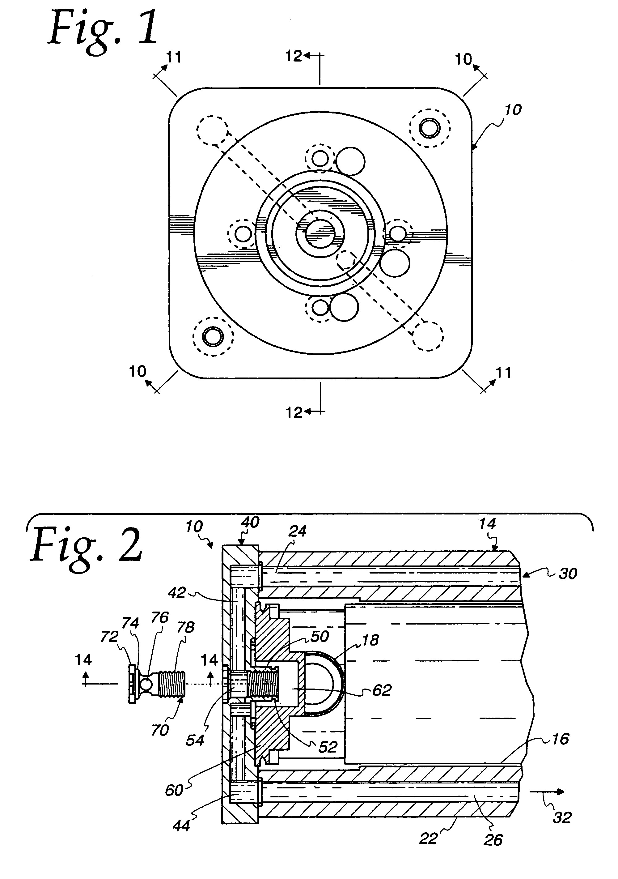
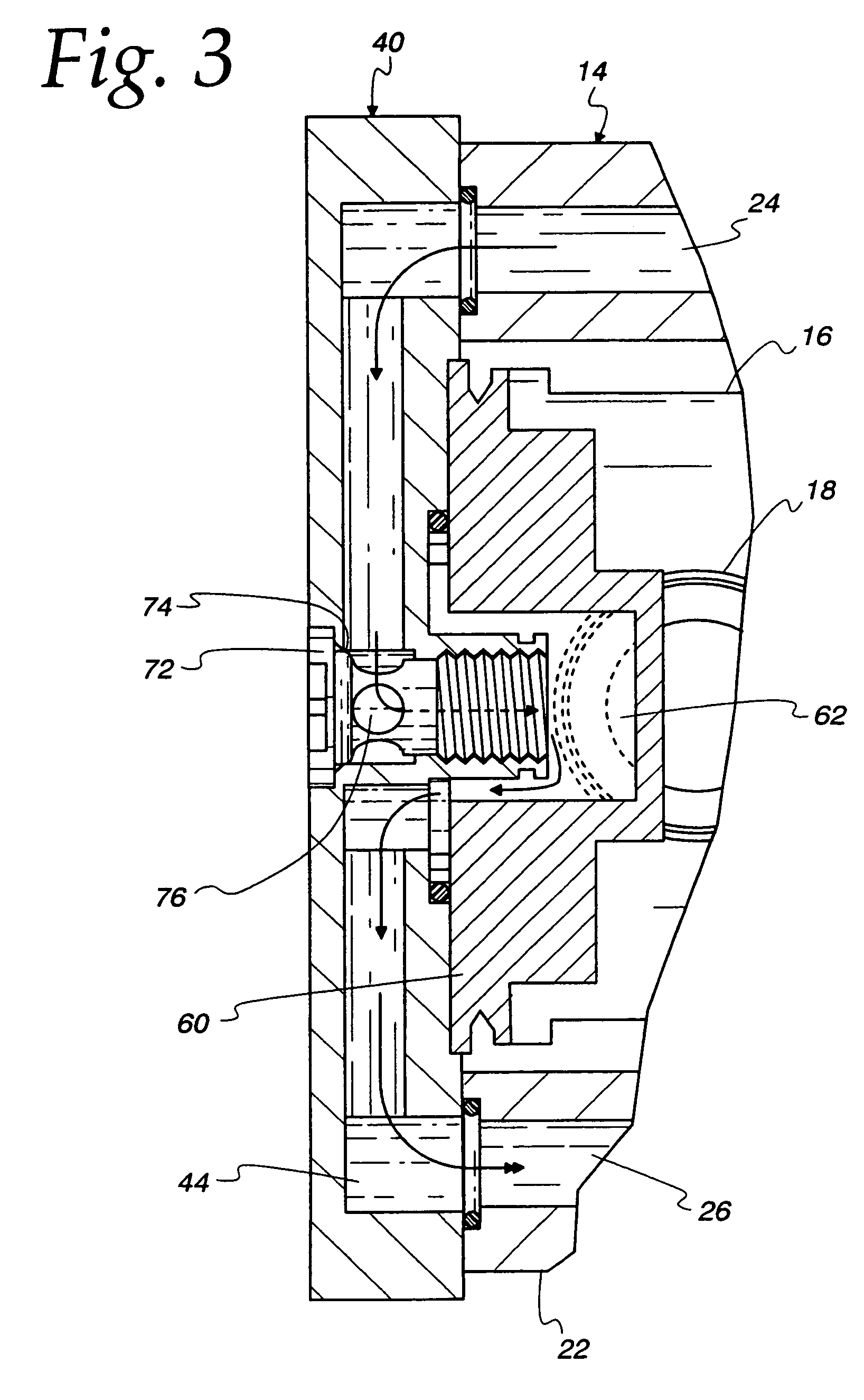
[0029]Turning now to the drawings and initially to FIGS. 1–3, an X-ray emitting device is generally indicated at 10. Device 10 preferably comprises an X-ray source, or goniometer or X-ray head assembly for use in X-ray diffraction analysis. A representative test set-up is shown in FIG. 18 including a typical X-ray head assembly in which the present cooling system can be incorporated. Generally, the head assembly will include a collimator 13 depending from the forward end portion thereof for directing X-rays at part such as the illustrated gear 15 rigidly held by fixturing 17 therebelow. The head assembly 10 along with its collimator 13 is commonly driven in an arcuate path 170 so that X-rays are directed at the region on the part 15 to be tested from a variety of different angles to provide several different data points from which X-ray diffraction measurement information can be gleaned. In addition to the collimator 13, X-ray detector assembly 19 is carried by the head assembly 10 ...


PUM

PropertyMeasurementUnit
energyaaaaaaaaaa
residual stressesaaaaaaaaaa
sizeaaaaaaaaaa

Abstract

A cooling system is provided for high energy emitting devices such as employed in X-ray diffraction testing equipment. The cooling system includes a removable filter holder that carries a filter for being disposed in a cooling path formed in the X-ray head assembly with the holder including a detachable connection to the head. The removable holder allows for servicing of the filter without requiring significant disassembly operations on the X-ray head assembly. In the preferred form, the holder has a screw-type configuration and the detachable connection is a threaded connection to a cooling head portion of the X-ray head assembly.

Description

FIELD OF THE INVENTION[0001]The present invention pertains to cooling of devices that generate high energy emissions such as those used in X-ray diffraction analysis.BACKGROUND OF THE INVENTION[0002]Non-destructive testing utilizing X-ray diffraction techniques is playing an increasingly important role in measuring residual stresses and other material characteristics. Once limited to laboratory conditions, X-ray diffraction is now made available for use in the field to analyze parts and structures of unlimited size and in almost any location. Advances in the art made possible by the assignee of the present invention allows on-site investigation in practical working environments, that is, in spaces constrained by real world equipment. To this end, open beam-type X-ray diffraction equipment has been employed most effectively. In those systems, the X-ray goniometer head is cantilevered and carries fiberoptic detectors toward the forward end thereof. Nevertheless, in order to meet the d...

Claims


Application Information

Patent Timeline
Patent Type & Authority Patents(United States)
IPC IPC(8): H01J35/12G01N23/20H05G1/02
CPCB01D29/03B01D35/02H05G1/02B01D29/33H05G1/025B01D2201/02B01D2201/301
Inventor BRAUSS, MICHAEL
Owner PROTO MANUFACTURING LTD
Why Eureka
Try Eureka