
Electronic control unit for controlling updating of data in non-volatile memory

a technology of non-volatile memory and control unit, which is applied in the direction of memory adressing/allocation/relocation, instruments, transportation and packaging, etc., can solve the problem that the entry process of such dada to the non-volatile memory is no longer implemented during the present operation period, and the useless process of such dada is no longer implemented. to achieve the effect of reliable data storag

Active Publication Date: 2007-04-10
DENSO CORP
View PDF20 Cites 13 Cited by
  • Summary
  • Abstract
  • Description
  • Claims
  • Application Information

AI Technical Summary

Benefits of technology

[0018]The present invention therefore has an object to effectively realize reduction in the number of times of data entry to a programmable non-volatile memory, and also reliable storage of data thereto in an electronic control unit. This unit continuously stores the data which is increased or decreased depending on the specified rule and is changed in the value by only N at a maximum during single operation period using the programmable non-volatile memory.

Problems solved by technology

Moreover, when the entry of continuous storage object data to the non-volatile memory is completed, useless process for entry of such dada to the non-volatile memory is no longer implemented during the present operation period.

Method used


Image

  • Electronic control unit for controlling updating of data in non-volatile memory
  • Electronic control unit for controlling updating of data in non-volatile memory
  • Electronic control unit for controlling updating of data in non-volatile memory

Examples


first embodiment

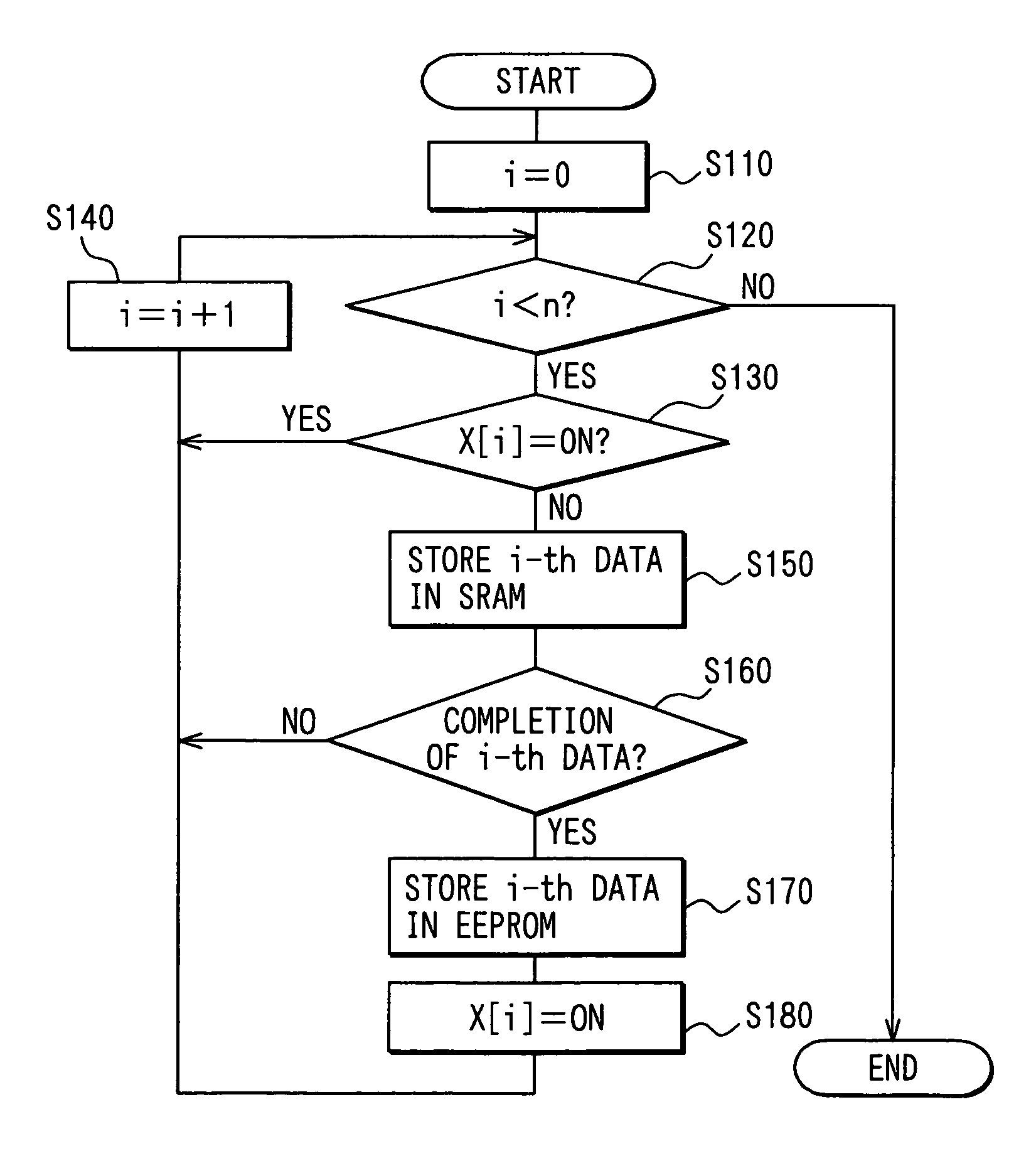
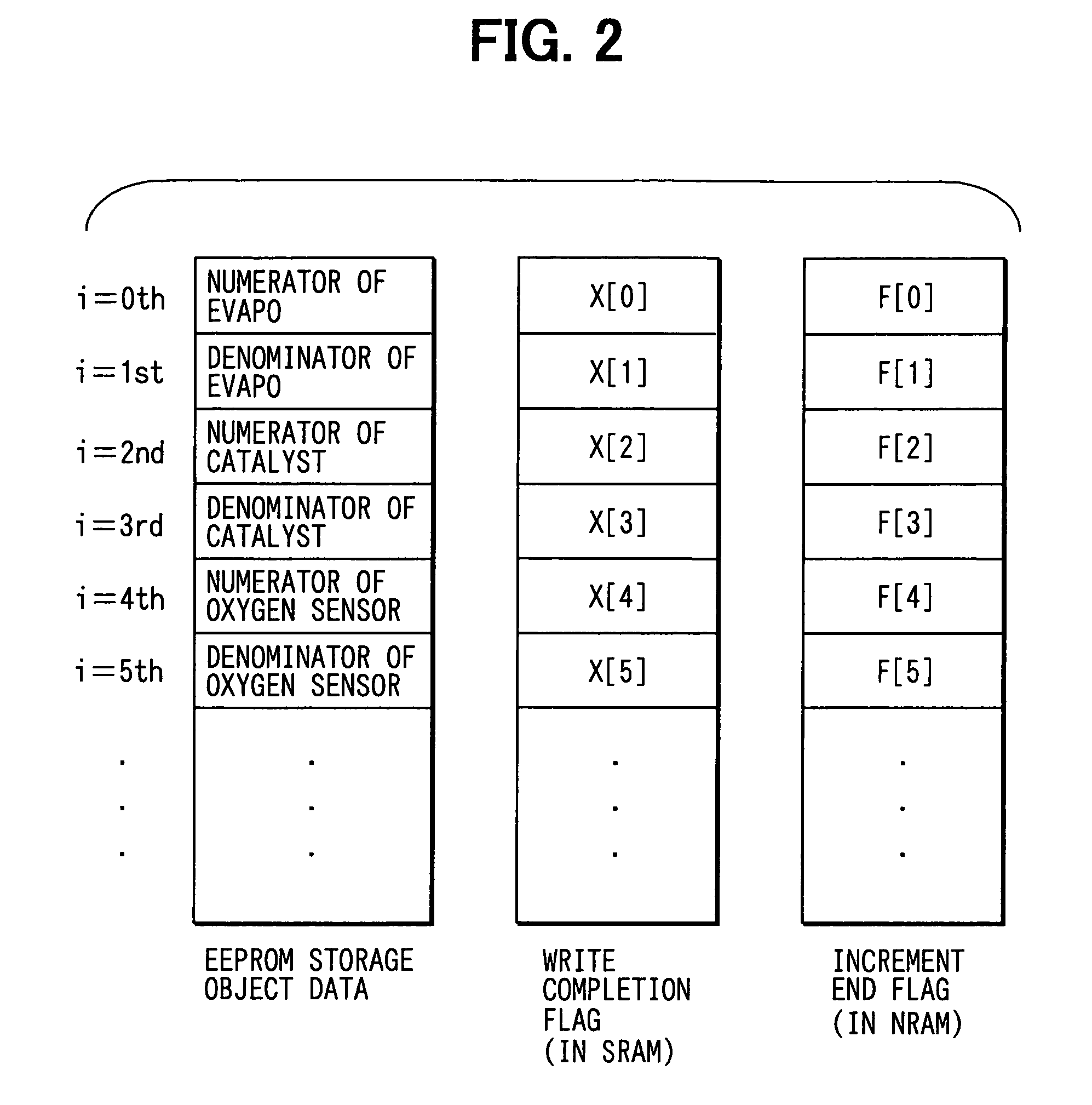
[0067]In the ECU 1 of the first embodiment, when any continuous storage object data is incremented only by one (1) (step 160: YES) in the single operation period of the ECU 1 through execution of the routine process of FIG. 4 by the microcomputer 7, the write process (step 170) to write the incremented data to the EEPROM 11 is implemented. Moreover, the process to write the data to the EEPROM 11 is not implemented during the subsequent operation period by turning on (Step 180) the write completion flag X[i] for such data (Step 130: YES→Step 140).

[0068]Therefore, according to the ECU 1 of the first embodiment, the number of times of data entry to the EEPROM 11 of the continuous storage object data can be controlled. In addition, the data entry to the EEPROM 11 of the continuous storage object data (in more detail, the continuous storage object data having reached the final value in the present operation period through increment of one (1)) can be implemented during the present operat...

second embodiment

[0076]Next, the ECU of a second embodiment will be described.

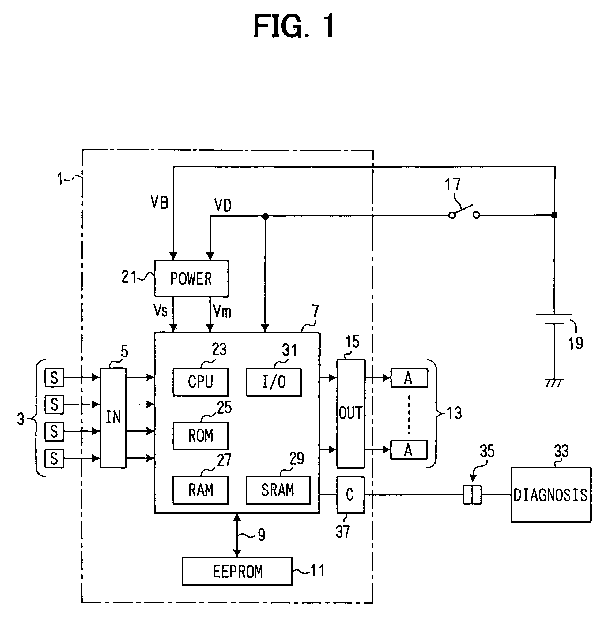
[0077]First, FIG. 6 is a block diagram showing a structure of the ECU 41 of the second embodiment. The ECU 41 of the second embodiment is also provided to control the engine of vehicle. In FIG. 6, the like elements of the ECU 1 (FIG. 1) of the first embodiment are designated with the like reference numerals and the detail description thereof will be omitted here.

[0078]As illustrated in FIG. 6, the ECU 41 of the second embodiment is different in the following points (1) to (5) from the ECU 1 of the first embodiment.[0079](1) The operation power source voltage VD from the battery 19 is supplied via a main relay 43 as a switching device for power feeding provided at the external side of the ECU 41, not via the ignition switch 17. That is, when the main relay 43 turns on (in more detail, contact of the main relay 43 is closed), the operation power source voltage VD is supplied to the power supply circuit 21 from the battery 19...


PUM


Abstract

An electronic control unit continuously stores data indicating the monitoring frequency of the diagnosis items determined by the RateBase monitoring method and is increased one by one with the maximum amount of change in the single operating period to an EEPROM. When any data is incremented by one, this data is entered to the EEPROM and the write completion flag for this data is turned on. Thereafter, in this operating period, this data is never entered to the EEPROM. Therefore, reduction and increase in the number of times of data entry to the programmable non-volatile memory and reliable storage of this data can be realized effectively.

Description

CROSS REFERENCE TO RELATED APPLICATION[0001]This application is related to and incorporates herein by reference Japanese Patent Application No. 2002-305813 filed on Oct. 21, 2002.FIELD OF THE INVENTION[0002]The present invention relates to an electronic control unit for storing particular data to be updated or rewritten during its operation into a non-volatile memory, which is available for electrical update or updating of the data but has a limitation on the number of times of data entry.BACKGROUND OF THE INVENTION[0003]Conventional electronic control units for a vehicle are so constructed as to write particular data into an BEPROM (electrically-erasable and programmable read only memory) available for use in electrically updating the data. The particular data may be diagnostic information and control learning values etc. required to be continuously stored even if the supply of operation power source is suspended. This data is referred to as continuous storage object data. The elec...

Claims


Application Information

Patent Timeline
Patent Type & Authority Patents(United States)
IPC IPC(8): G06F12/10B60R16/02G06F12/16G11C16/02
CPCG11C5/143G11C11/005G11C16/10
Inventor OKADA, KAZUNORI
Owner DENSO CORP
Learn More