Track and punch SMR marking device

a marking device and retroreflector technology, which is applied in the field of punching devices, can solve the problems of not being able to facilitate the highly accurate use of punches, not being able to achieve high accuracy, and not the end result, etc., and achieves the effect of precise punching and adding to the high accuracy of any machining operation

Inactive Publication Date: 2007-04-17
HUBBS WILLIAM O
View PDF15 Cites 6 Cited by
  • Summary
  • Abstract
  • Description
  • Claims
  • Application Information

AI Technical Summary

Benefits of technology

[0013]This invention related principally to a track and punch device, utilizing a spherically mounted retro-reflector, that is mounted in a nest, for providing very precise punching upon a part to be worked, so as to add to the high accuracy of any machining operation performed.
[0018]It is, therefore, the principal object of this invention to provide a highly precise punching device that cooperates with the laser tracker, and a spherically mounted retro-reflector, for demarcating a point upon any part to be further worked, as by drilling, or the like.
[0019]Still another object of this invention is to provide a conveniently and compact type of marking device, readily disposing a striker for manipulating to furnish a punch point on a component to be further worked.
[0020]Still another object of this invention is to provide means for mounting of a spherically mounted retro-reflector to a punching device, and through cooperating with guidance means, such as a laser tracker, affords its precise setting for marking a component to be further machined.

Problems solved by technology

These devices may undertake configuration of nothing more than a punch, that can be lowered into a marking position, provide a slight indentation into the part to be worked, such as by drilling, etc., but obviously precision is not the end result, nor is obtained, with these types of earlier devices.
But, it does not appear to be used for facilitating the highly accurate usage of a punch, as for drilling and related purposes.

Method used


Image

  • Track and punch SMR marking device
  • Track and punch SMR marking device
  • Track and punch SMR marking device

Examples


Embodiment Construction

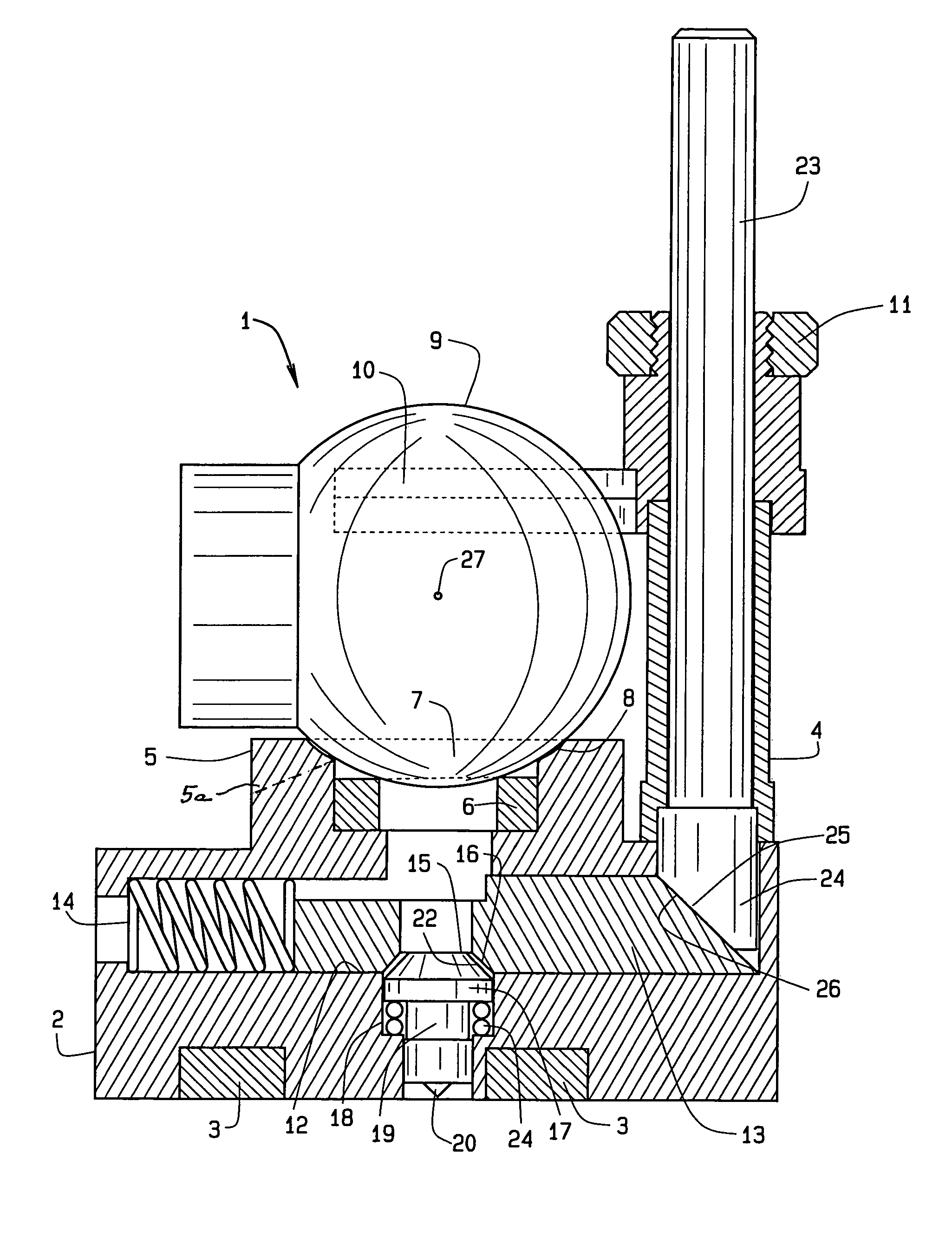
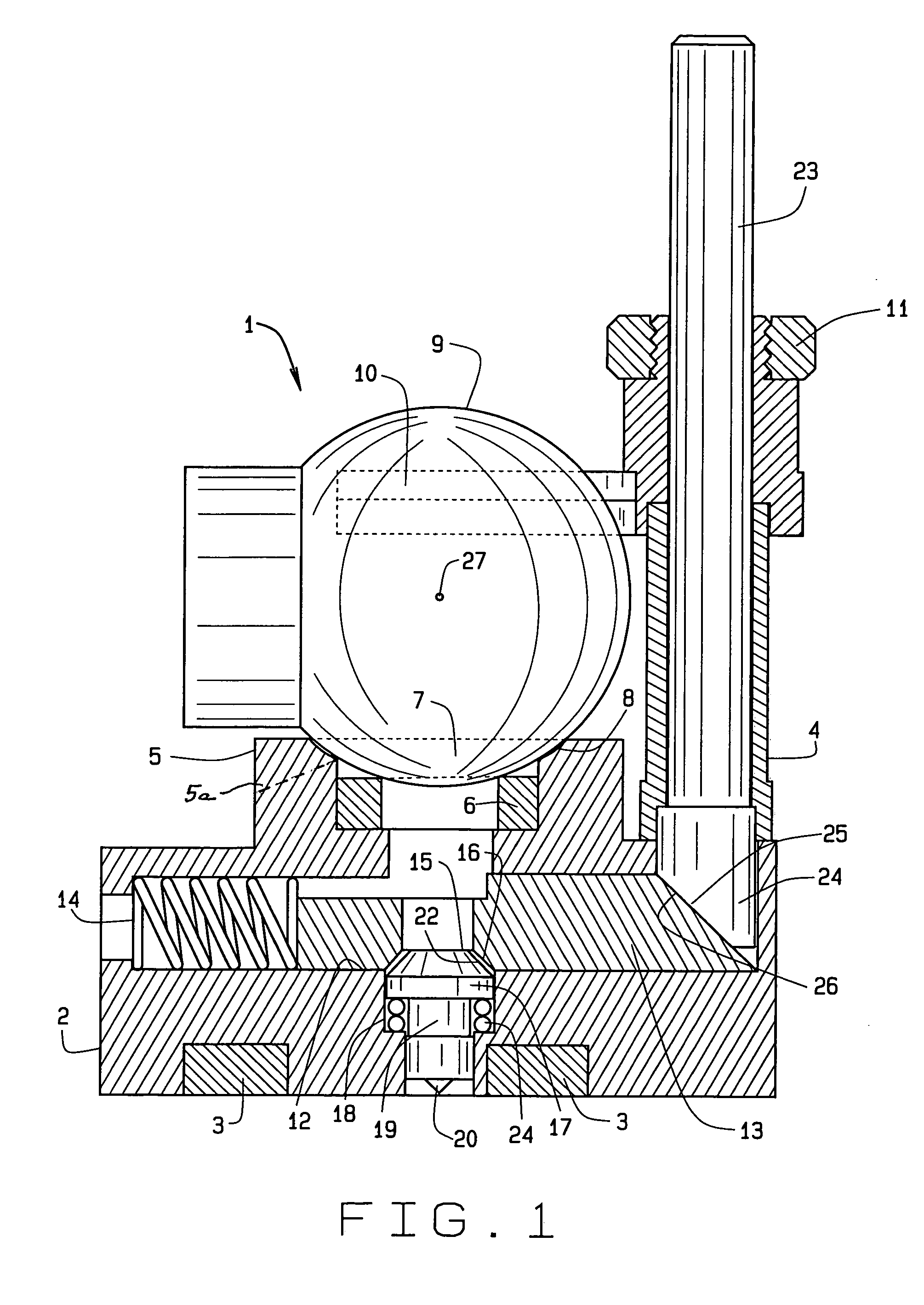
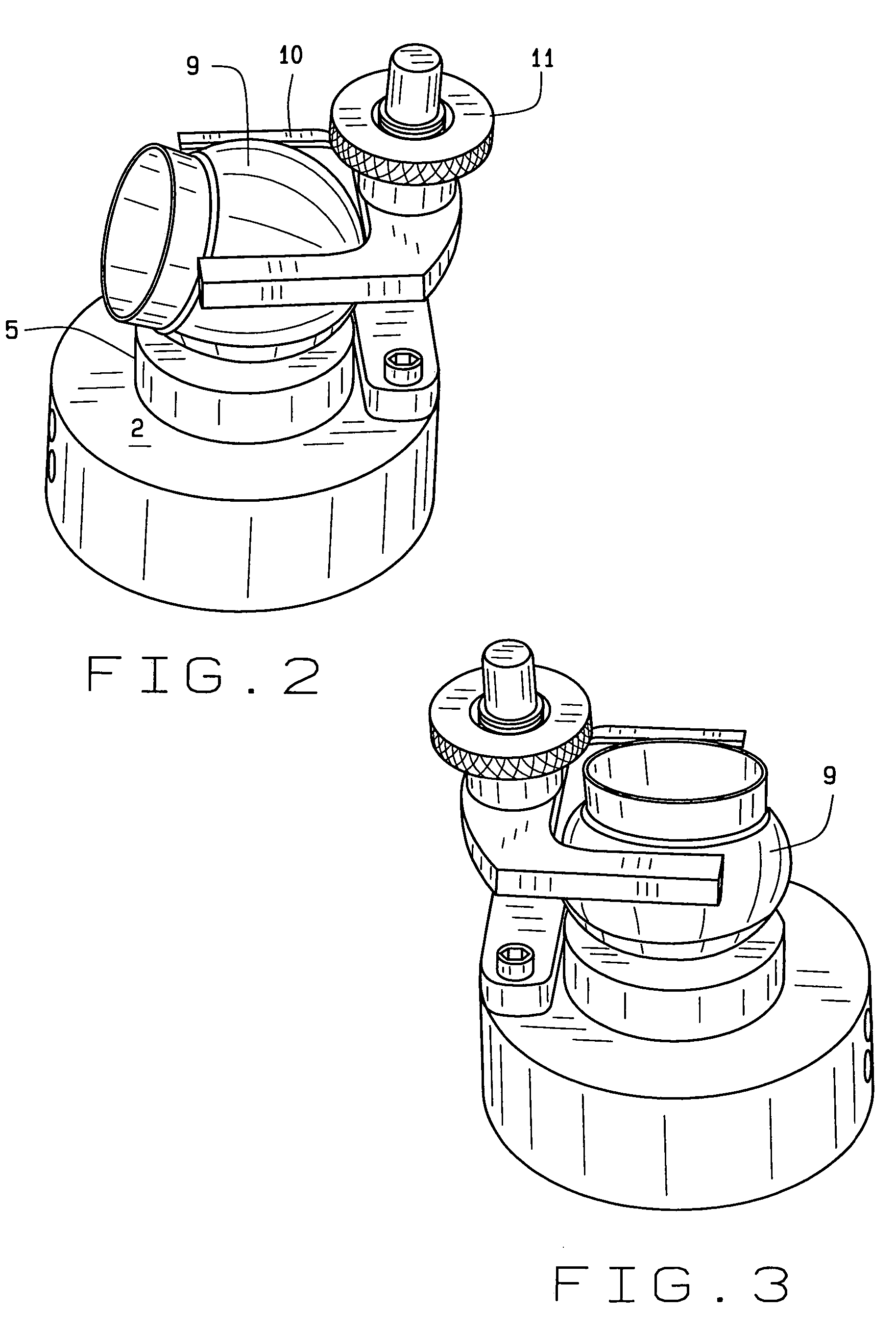
[0030]In referring to the drawings, and in particular FIG. 1, the track and punch SMR marking device of this invention is readily disclosed, as at 1. The structure includes a base member 2 which has embedded therein one or more magnets 3 which are designed for temporarily affixing the device to the surface to be marked, and if it is of a metallic substance, the magnets aid in holding the set device in place. Extending upwardly is an attached sleeve 4, as can be noted, extending upwardly from the approximate back end of the base 2.

[0031]The base includes an upwardly extending integral portion 5, which includes a further magnet 6 provided within a counterbore, and has an opening 7 furnishing slightly beveled edges 8, around its perimeter, and it is designed to provide for sliding seating a spherically mounted retro-reflector 9 as can be noted. A magnet retainer clip 6a provides for retention of the magnet in place. In addition, negative rotation notch 5a, provided at the front of the ...


PUM

PropertyMeasurementUnit
perimeteraaaaaaaaaa
pressureaaaaaaaaaa

Abstract

A track and punch SMR marking device, including a base, the base mounts for adjustment an SMR (spherically mounted retro-reflector), which in cooperation with a laser tracker beam locates the device precisely over an area where a punch mark is to be made, the base includes an upright sleeve, for holding a striker shaft, the striker shaft, at its lower end, includes a bevel, mating with the inclined surface of a cross slide, the cross slide, when it is urged forwardly, depresses a punch forcing it downwardly so as to provide a punch point or indentation upon the component to be worked.

Description

CROSS REFERENCE TO RELATED APPLICATION[0001]This continuation patent application claims priority to the non-provisional patent application having Ser. No. 10 / 640,285, which was filed on Aug. 13, 2003, now abandoned which claims priority to the provisional patent application having Ser. No. 60 / 404,546, which was filed on Aug. 20, 2002.BACKGROUND OF THE INVENTION[0002]This invention relates generally to a punching device, and more specifically, to a particularly constructed track and punch spherically mounted retro-reflector marking device for use for providing precision marking of a component to be drilled, or the like.[0003]A variety of center punching devices and assemblies have long been available in the art. These devices may undertake configuration of nothing more than a punch, that can be lowered into a marking position, provide a slight indentation into the part to be worked, such as by drilling, etc., but obviously precision is not the end result, nor is obtained, with these ...

Claims


Application Information

Patent Timeline
Patent Type & Authority Patents(United States)
IPC IPC(8): B26F1/00B25D5/02
CPCB25D5/02Y10T83/929Y10T83/9418
Inventor HUBBS, WILLIAM O.
Owner HUBBS WILLIAM O
Why Eureka
Try Eureka