Exit device with lighted touchpad

a technology of exit device and touchpad, which is applied in the direction of mechanical equipment, instruments, transportation and packaging, etc., can solve the problems of inability of those within the building to quickly respond, the location is the first to become obscured, and the death of public buildings. , to achieve the effect of simplifying removal, repair and replacemen

Inactive Publication Date: 2007-04-17
SARGENT MANUFACTURING CO INC
View PDF42 Cites 25 Cited by
  • Summary
  • Abstract
  • Description
  • Claims
  • Application Information

AI Technical Summary

Benefits of technology

[0010]It is another object of the present invention to provide an exit device with an integrated illuminated sign assembly that is long lasting and impact resistant.
[0015]The sign assembly is preferably mounted on the actuator such that pressure applied directly to the illuminated sign assembly will operate the exit device. The sign assembly may be directly mounted on the actuator or it may be mounted on a touchpad mounted on the actuator. The touchpad may provide additional electrical insulation and may simplify removal, repair and replacement of the sign assembly and the components thereof.

Problems solved by technology

Although exit devices have been highly successful in performing the function for which they were designed, deaths in public building fires continue to occur.
Some deaths can be traced to the inability of those within the building to quickly identify all the building exit doors when smoke from the fire obscures required exit signage.
However, this location is the first to become obscured when smoke and heated air from a fire rise to the ceiling in the room.
Conventional illumination devices, which might meet this need, such as incandescent bulbs, are bulky, fragile, provide non-uniform illumination and produce excessive heat, all of which makes them unsuitable for installation in an exit device.
An exit device is subject to repeated impact as the door is operated, so any illuminator located therein must be extremely rugged.
The illuminator must not produce heat which could potentially burn a user touching metal components of the exit device, or which might present a fire hazard when the exit device is installed on a wooden door.

Method used


Image

  • Exit device with lighted touchpad
  • Exit device with lighted touchpad
  • Exit device with lighted touchpad

Examples


Embodiment Construction

)

[0022]In describing the preferred embodiment of the present invention, reference will be made herein to FIGS. 1–2 of the drawings in which like numerals refer to like features of the invention.

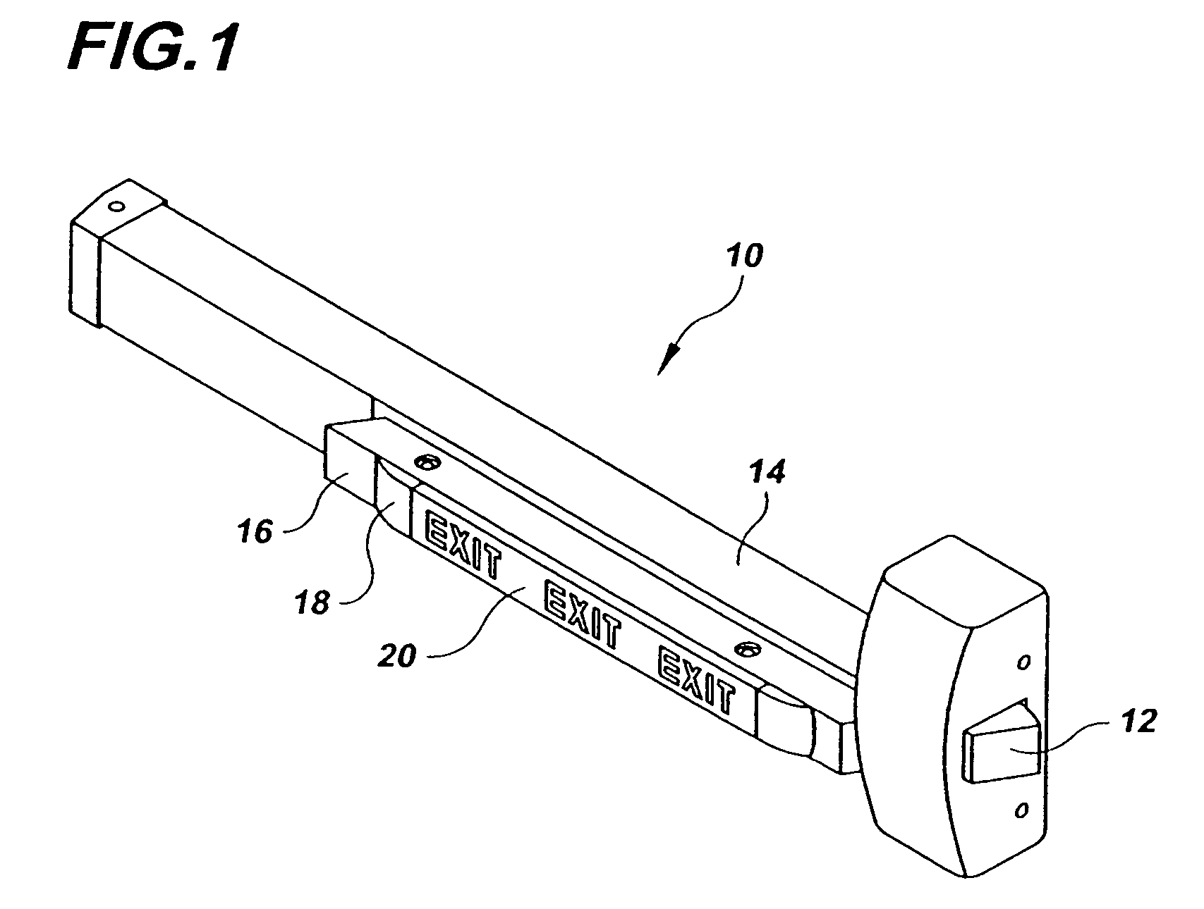
[0023]Referring to FIG. 1, an illuminated exit device 10 includes a door latch mechanism 12, a base 14 for attachment to a surface of a door, and an actuator 16 movably mounted relative to the base and connected to operate the latch mechanism 12. When pressure is applied directly to the actuator 16, to the touchpad 18 or to an integrated electroluminescent sign assembly 20, the latch mechanism is operated to open the exit door.

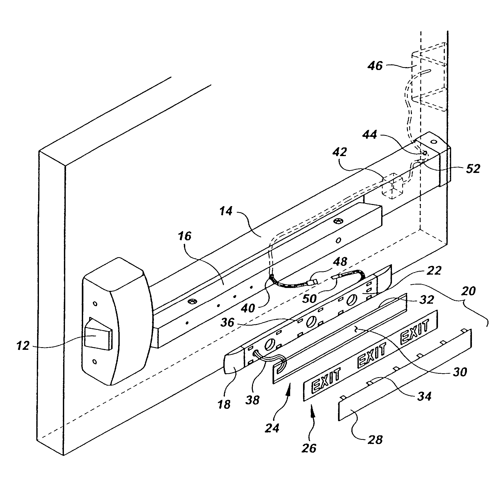
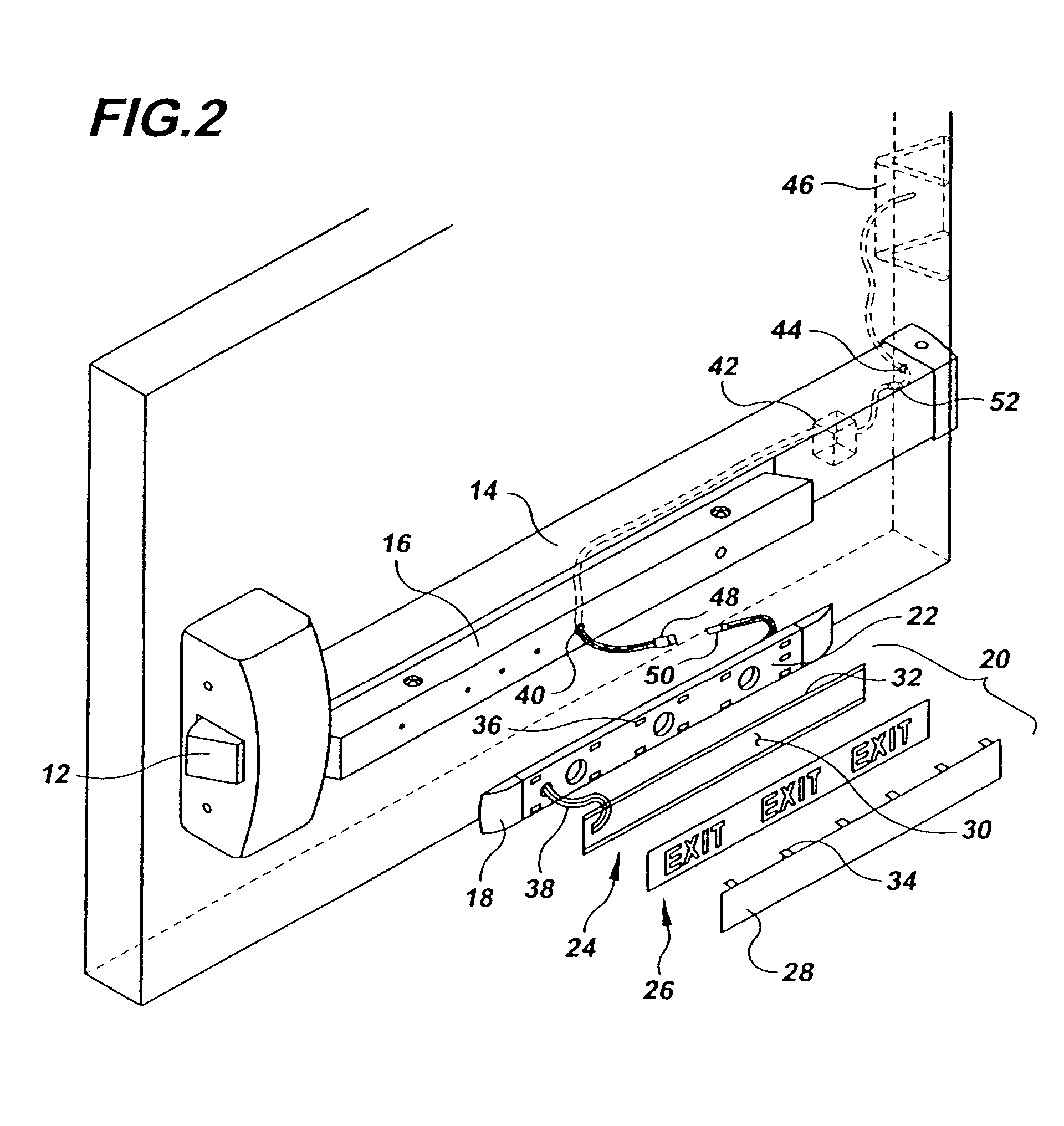
[0024]Referring to FIG. 2, it can be seen that the actuator 16 is provided with a touchpad 18 having a surface cavity 22 formed therein for receiving the sign assembly 20. The sign assembly 20 is formed from a planar electroluminescent illuminator 24, a planar sign 26 having opaque portions to form the readable sign and a transparent protective cover 28.

[0025]The electr...


PUM


Abstract

An exit device includes an electroluminescent exit sign assembly, preferably mounted on a push rail actuator of the exit device. An electroluminescent illuminator, an opaque material and a transparent protective cover form the electroluminescent sign assembly. The push rail actuator operates a latch mechanism and opens an associated exit door when pressure is applied. An inverter may be located within the exit device to power the electroluminescent illuminator with an AC or voltage. The electroluminescent sign assembly is preferably removable for repair or replacement without removing the exit device from the exit door and is located within a surface cavity in an electrically insulating touchpad on the exit device actuator. Additional transparent nonconductive material surrounds the electroluminescent material to provide further electrical insulation.

Description

BACKGROUND OF THE INVENTION[0001]1. Field of the Invention[0002]The present invention relates to exit devices, of the type used to rapidly and reliably open exit doors and allow people to exit public buildings in the event of a fire, panic situation or other emergency. More particularly, the present invention relates to electrically illuminated exit devices.[0003]2. Description of Related Art[0004]An “exit device” is a lock mechanism operated from the inside of an outward swing door through the use of a crossbar, push bar or push rail actuator, that is designed to open an exit door, allowing exit without prior knowledge of how the lock operates, whenever a horizontal force is applied to the actuator. Exit devices are typically required by fire or building codes and are used in public buildings where many people may be gathered, to provide rapid, safe and easy egress in case of emergency.[0005]Exit devices ensure that an exit door is free to operate from the inside of the locked area...

Claims


Application Information

Patent Timeline
Patent Type & Authority Patents(United States)
IPC IPC(8): G09F13/04G09F13/22
CPCG09F13/04G09F13/22Y10S362/812E05B17/10E05B65/1053Y10T292/0909Y10T292/57
Inventor MOLOKOTOS, THANASISPICARD, DANIEL J
Owner SARGENT MANUFACTURING CO INC
Why Eureka
Try Eureka