Supercharge Your Innovation With Domain-Expert AI Agents!

Equalizing flapper for high slam rate applications

a flapper valve and high slam rate technology, applied in the direction of sealing/packing, pressure relieving devices on the sealing face, borehole/well accessories, etc., can solve the problems of difficult to open a flapper valve that has been closed by a high pressure differential, fluid pressure holding the valve member in the closed position can be very difficult to overcome, and the valve assembly may not be well suited to high slam rate applications

Active Publication Date: 2007-04-17
BAKER HUGHES INC
View PDF9 Cites 20 Cited by
  • Summary
  • Abstract
  • Description
  • Claims
  • Application Information

AI Technical Summary

Benefits of technology

The invention is an improved design for a flapper valve used in subterranean wellbores or flow situations. It is particularly suitable for high-rate, high-pressure differentials. The flapper valve has an equalizing port assembly with a bleed valve and a retainer key to ensure fluid flow. It also has raised actuator contact portions to prevent material deformation and a dual counterbore design to prevent metal from flowing onto the equalization valve member. The equalizing valve assembly provides a more secure and suitable valve arrangement for high slam applications.

Problems solved by technology

It is, however, difficult to open a flapper valve that has been closed by a high pressure differential.
The fluid pressure holding the valve member in the closed position can be very difficult to overcome.
While effective, these valve assemblies may not be well suited to high slam rate applications where the dynamic forces are so significant that they can damage the equalization valve element during closing (i.e., slamming) of the flapper.
A particular problem that has been observed with prior art equalization valve assemblies is that the poppet valve components for the equalization valve assembly can be damaged as the flapper is slammed closed by fluid flow.
As a result, the flapper may be unable to fully close off fluid flow as it is intended to do.
Neither of these arrangements is sufficiently robust to effectively resist potential damage during high slam rate applications.
Additionally, a cantilevered beam may be unsuitable for effectively biasing closed the equalizing valve because the beam member may not have adequate shape memory, in the manner that a compression spring would have.
As a result, the equalizing port may not be fully closed in the absence of a significant pressure differential and may tend to leak fluid in any event.
A related problem with conventional equalizing flapper assemblies stems from damage caused to the upper (downstream) face of the flapper valve member from contact by the actuating sleeve.
When a smaller, curved area of metal contacts the lower end of the actuating sleeve, the forces necessary to open the flapper element often deform the metal of the flapper element.
Because the equalization valve is normally aligned with the lower end of the actuating sleeve, deformed metal can flow onto the equalization valve member itself, causing the valve member to become non-functional.

Method used


Image

  • Equalizing flapper for high slam rate applications
  • Equalizing flapper for high slam rate applications
  • Equalizing flapper for high slam rate applications

Examples


Embodiment Construction

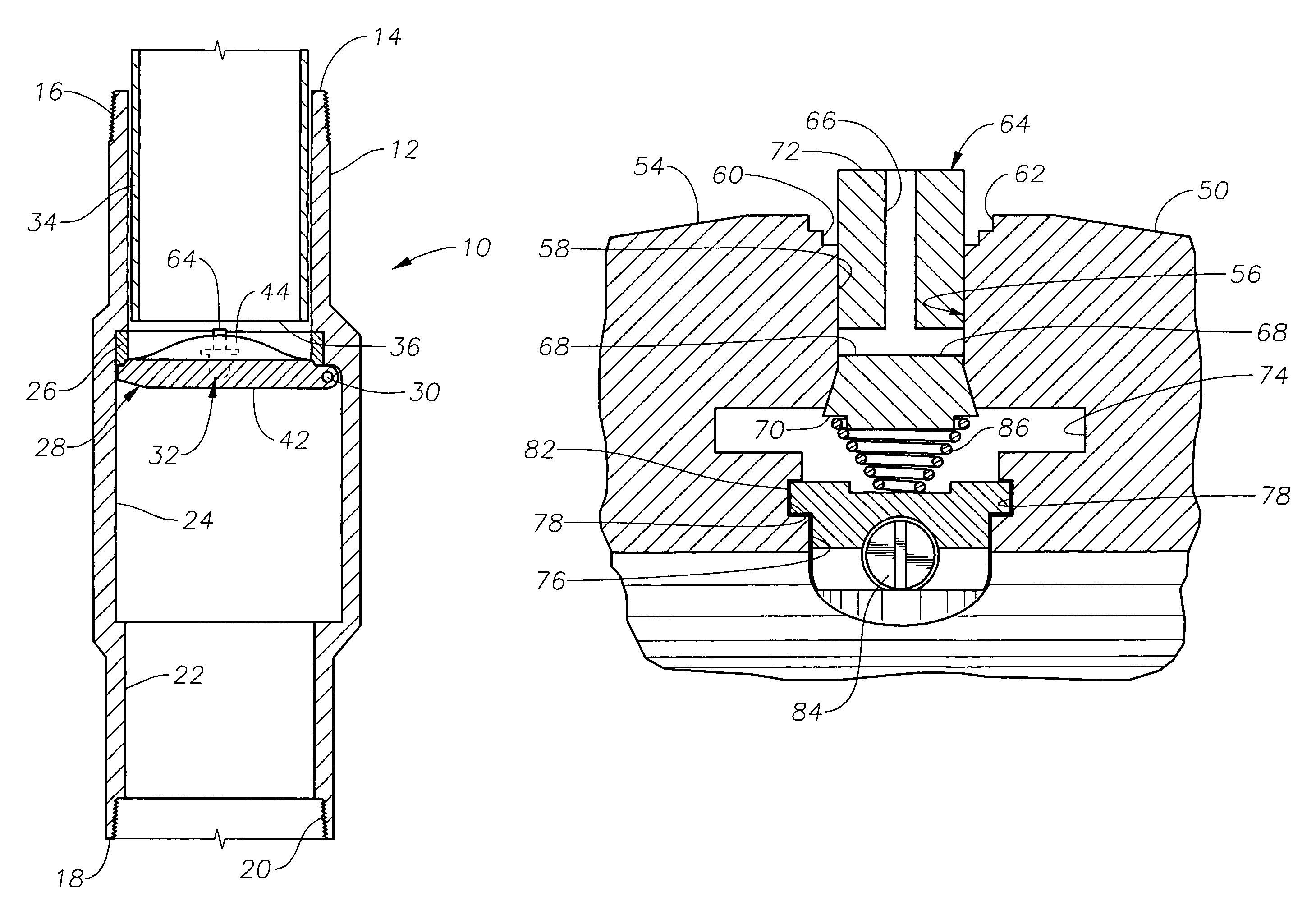
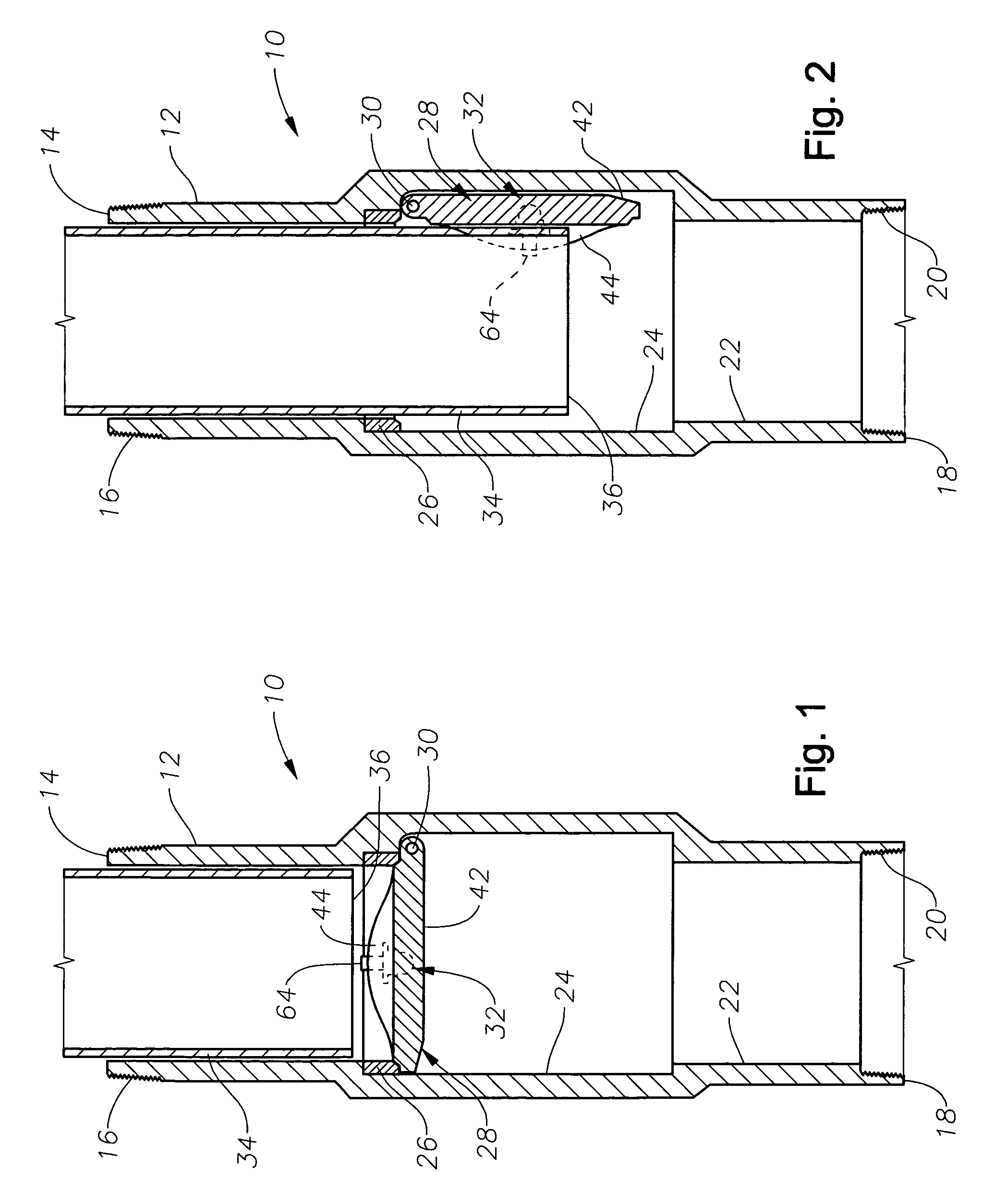
[0019]FIGS. 1 and 2 depict an exemplary equalizing flapper valve assembly 10 that is constructed in accordance with the present invention. The valve assembly 10 is typically incorporated into a production tubing string within a wellbore and used as a safety valve. The valve assembly 10 includes a valve housing 12 having a first axial end 14 with pin-type threading 16 for attachment to an adjacent section of production tubing (not shown) and a second axial end 18 with box-type threading 20 for attachment to an adjacent section of tubing (not shown). The valve housing 12 defines an axial flowbore 22 along its length having an enlarged central section 24. An annular valve seat 26 is secured within the enlarged central section 24. In this instance, it is desired to block fluid flowing from the second end 18 toward the first end 14. Therefore, the second end 18 will be considered to be upstream from the first end 14.

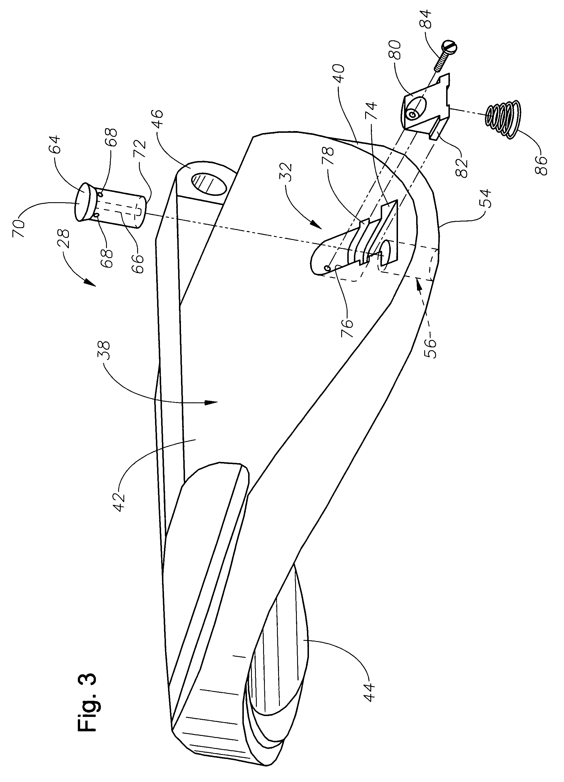
[0020]A flapper valve member 28 is hingedly secured to the valve seat 26...


PUM


Abstract

A flapper valve assembly is described having an equalizing port assembly with a bleed valve member that is moveable between an open position and a closed position. The equalizing port assembly features a structural support member in the form of a retainer key that is secured to the flapper valve member both axially and radially. Additionally, a compressible spring is located between the structural support member and provides biasing force upon the valve member to urge it toward a closed position. Additionally, the flapper valve member presents a pair of raised, substantially flat actuator contact portions upon its downstream face to meet an actuating tube in a mating contact arrangement and resist material deformation that could tend to clog or block the equalizing fluid flow port.

Description

BACKGROUND OF THE INVENTION[0001]1. Field of the Invention[0002]The invention relates generally to equalizing flapper type valves that are used, for example, as subsurface safety valves.[0003]2. Description of the Related Art[0004]Wellbores often include subsurface safety valves used to close off a section of production tubing in the event of an emergency. Flapper valve assemblies have long been employed as safety valves. Flapper valve assemblies typically consist of a curved metal valve member that is shaped to seat upon an annular valve seat within the tubing flowbore to block fluid flow through the flowbore. The valve member is hingedly attached to the inside of the tubing and rotates about the hinge point between open and closed positions. A closed flapper valve is usually opened by an axially shiftable actuation sleeve that contacts the downstream face of the flapper valve and urges the valve member toward its open position. It is, however, difficult to open a flapper valve tha...

Claims


Application Information

Patent Timeline
Patent Type & Authority Patents(United States)
IPC IPC(8): E21B34/14
CPCE21B34/101F16K15/181F16K39/024E21B2034/005E21B2200/05F16K15/1821
Inventor WILLIAMS, RONALDMCVICKER, VANSTRATTAN, SCOTTIVES, JASON B.
Owner BAKER HUGHES INC
Features
  • R&D
  • Intellectual Property
  • Life Sciences
  • Materials
  • Tech Scout
  • Unparalleled Data Quality
  • Higher Quality Content
  • 60% Fewer Hallucinations
Learn More