Ring-spinning system for making yarn having a magnetically-elevated ring

a spinning system and spinning ring technology, applied in the field of spinning systems for manufacturing yarns, can solve the problems of low production rate, low quality of yarn, and high production rate of non-continuous spinning systems

Inactive Publication Date: 2007-04-17
AUBURN UNIV
View PDF8 Cites 3 Cited by
  • Summary
  • Abstract
  • Description
  • Claims
  • Application Information

AI Technical Summary

Problems solved by technology

Continuous spinning systems generally produce high-quality yarn, and a wide diversity of yarn styles, but suffer from a low productivity rate.
On the other hand, non-continuous spinning systems generally have high production rates, but produce relatively low-quality yarn.
The main factor that limits the production rate of ring-spinning systems is the friction between the traveler and the ring.
Therefore, either the speed of the system must be kept below a certain limit to prevent damage to the traveler and / or the traveler will be damaged and will have to be replaced frequently.
Simultaneously using two different types of stabilizing forces to stabilize the ring complicates the ring-spinning system and makes the system unsuitable for industrial applications because the stabilizing forces tend to be difficult to control.
Moreover, the absence of a control system makes such systems uncontrollable in the case of start-up operation and in the case of yarn breakage.
In addition, the power required by such systems to provide the necessary air pressure and magnetic forces renders them unsuitable for industrial application because they are economically inefficient.

Method used


Image

  • Ring-spinning system for making yarn having a magnetically-elevated ring
  • Ring-spinning system for making yarn having a magnetically-elevated ring
  • Ring-spinning system for making yarn having a magnetically-elevated ring

Examples


Embodiment Construction

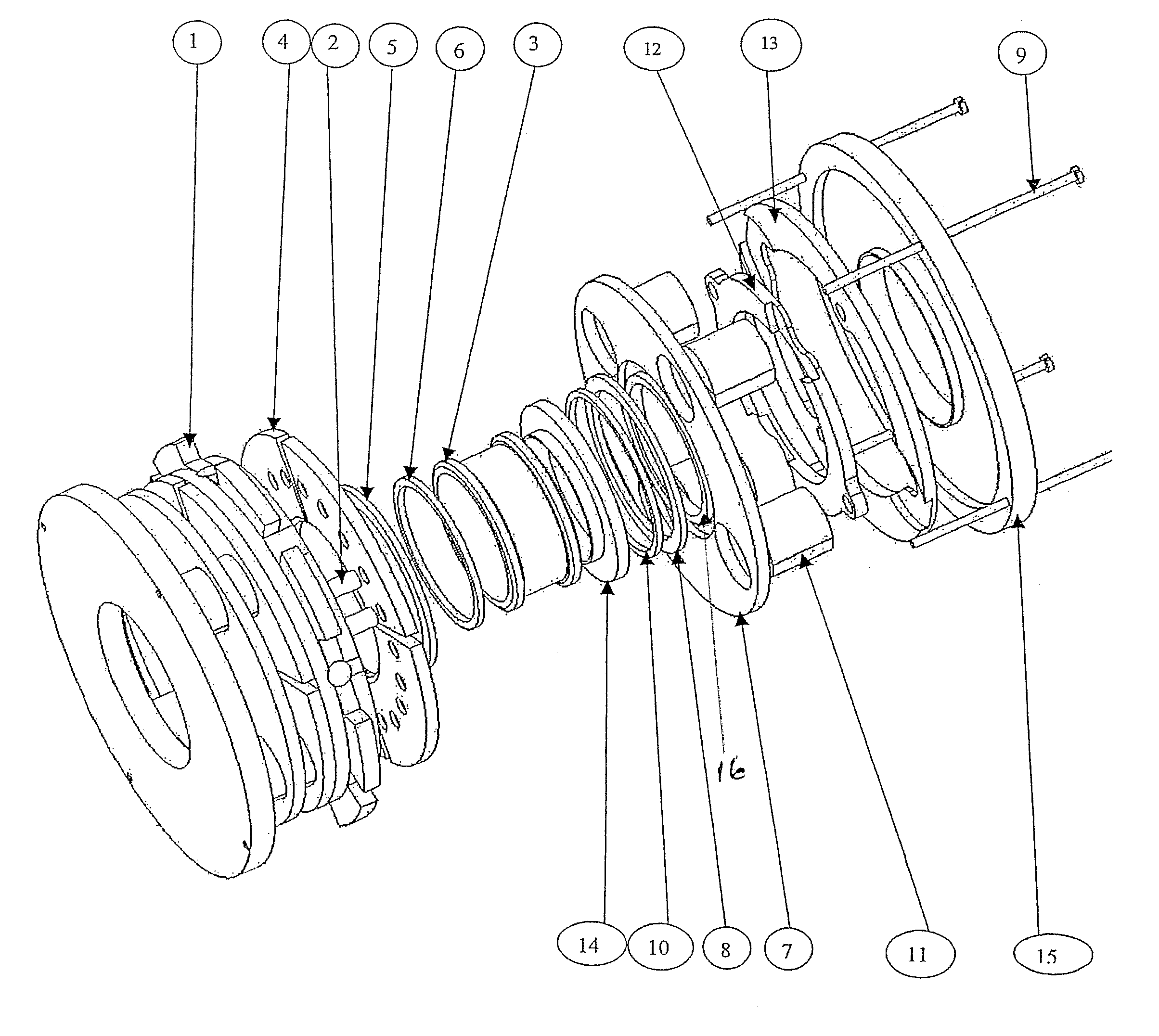
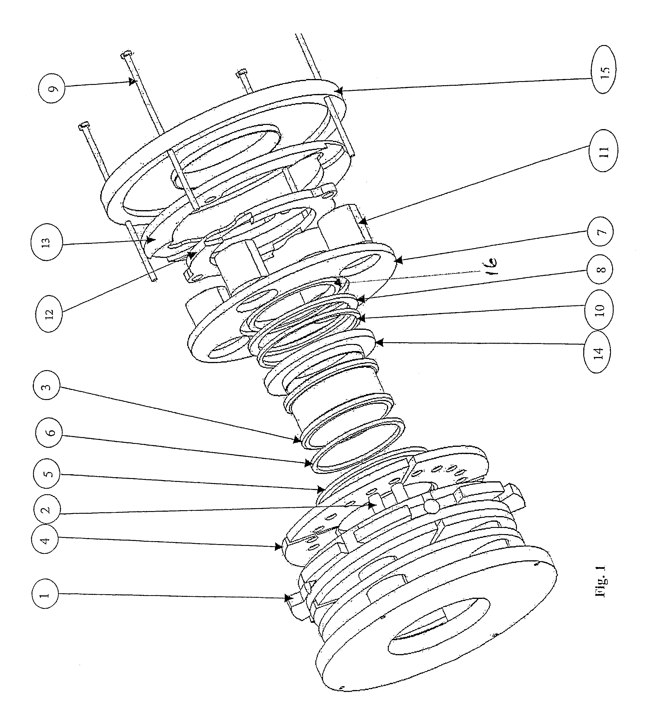
[0024]In accordance with the present invention, a magnetic ring-spinning device is provided that is capable of supporting a rotating ring in a stable manner around its center without touching the stator part. A rotating spinning ring has an eye that performs the functions equivalent to those performed by the traveler in a conventional ring-spinning system. The ring having the eye will be referred to herein as the “floating ring”. This floating ring 3 preferably has a form of a short cylinder with two flanges at its ends. The floating ring may be made from many materials, but preferably is made of a silicon steel material in accordance with the preferred embodiment of the present invention.

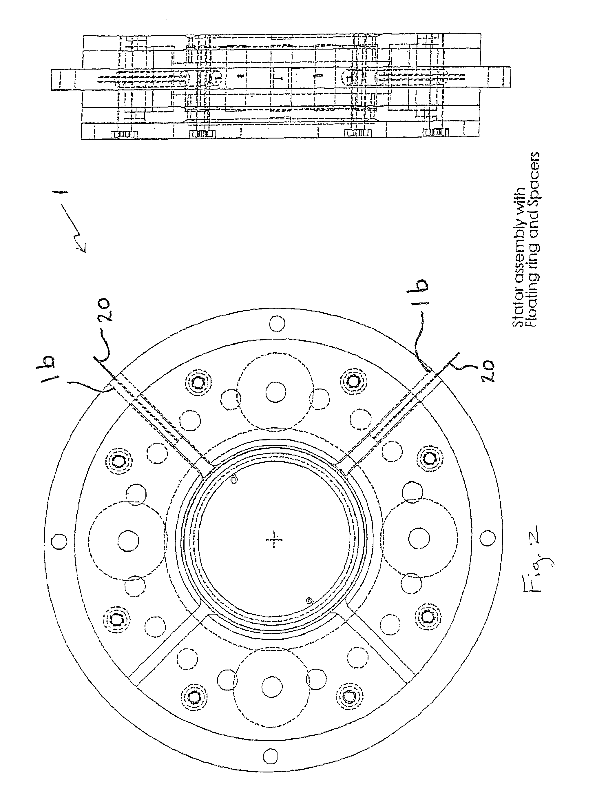
[0025]The components of the ring-spinning system in accordance with the preferred embodiment are shown in FIG. 1. The system comprises a stator 1 that has axial holes formed therein for receiving the cylindrical-shaped rare earth permanent magnets 2. The stator 1 also preferably has two radially-ex...


PUM

PropertyMeasurementUnit
air gap distanceaaaaaaaaaa
holding Z forceaaaaaaaaaa
forceaaaaaaaaaa

Abstract

A ring-spinning system for making yarn characterized in part by the replacement of the ring traveler configuration with only one rotating, floating ring that has an eye on its inner middle surface. This rotating, floating ring with the eye thereon performs the functions previously performed by the ring traveler configuration of twisting the fibers into yarn. The ring is kept suspended in space by the magnetic levitation system of the present invention. The floating ring is elevated by a well-controlled magnetic field generated by two sets of electromagnetic coils and a set of cylindrical rare earth permanent magnets. The floating ring is rotated around its center by the effect of winding the formed yarns over a rotating spindle at the center of the ring. Sensors and a feedback system are used to control the magnetic fields produced by the electromagnetic coils to maintain the ring in its central position.

Description

[0001]The U.S. Government has a paid-up license in this invention and the right in limited circumstances to require the patent owner to license others on reasonable terms as provided for by the terms of Grant No. 99-27-07400 awarded by the Department of Commerce and the National Textile Center.TECHNICAL FIELD OF THE INVENTION[0002]The present invention is related to manufacturing yarn from fiber strands and, more particularly, to a ring-spinning system for manufacturing yarn that employs a magnetically-elevated ring.BACKGROUND OF THE INVENTION[0003]Spinning is the process of forming yarns from fiber strands. The existing spinning systems may be divided into two main categories, namely, continuous spinning systems and non-continuous spinning systems. In continuous spinning, the fiber strand fed to the spinning system follows a continuous path throughout the entire spinning process from the feeding point to the yarn package. Ring spinning and compact spinning are two examples of conti...

Claims


Application Information

Patent Timeline
Patent Type & Authority Patents(United States)
IPC IPC(8): H02K7/09D01H7/56
CPCD01H7/56F16C32/044
Inventor ABDEL-HADY, FAISSALELMOGHAZY, YEHIA
Owner AUBURN UNIV
Why Eureka
Try Eureka