Power line communication using power factor correction circuits

a technology of power factor correction and power line communication, which is applied in the direction of electric variable regulation, process and machine control, instruments, etc., can solve the problems of prohibitively large components needed to capacitively couple or transformer couple the plc signal to the power lin

Active Publication Date: 2007-04-17
TEXAS INSTR INC
View PDF2 Cites 274 Cited by
  • Summary
  • Abstract
  • Description
  • Claims
  • Application Information

AI Technical Summary

Problems solved by technology

However, compared to PLC systems using higher frequencies (such as 132 kHz), the components needed to capacitively couple or transformer couple the PLC signal to the power line become prohibitively large.

Method used


Image

  • Power line communication using power factor correction circuits
  • Power line communication using power factor correction circuits
  • Power line communication using power factor correction circuits

Examples


Embodiment Construction

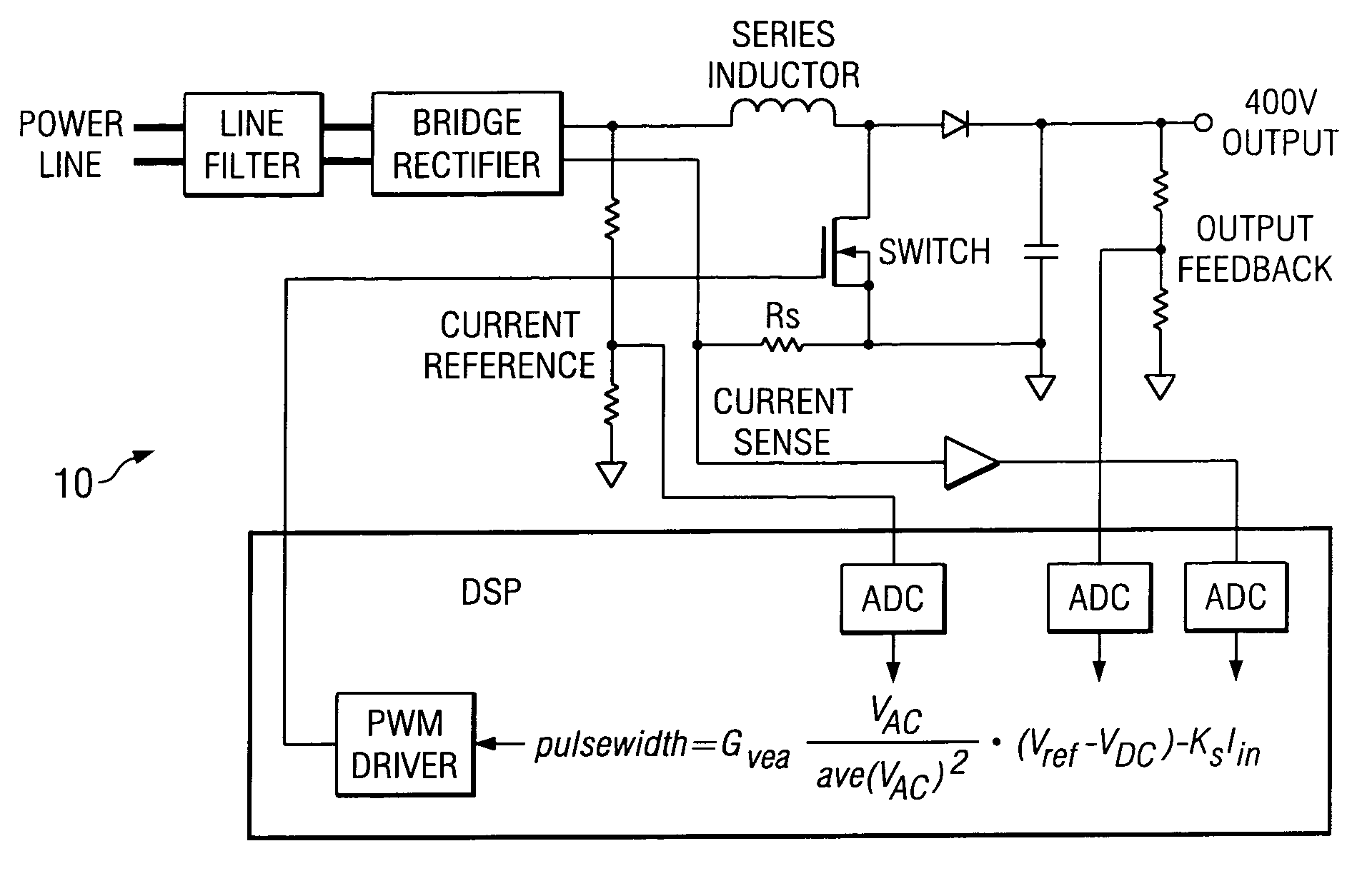
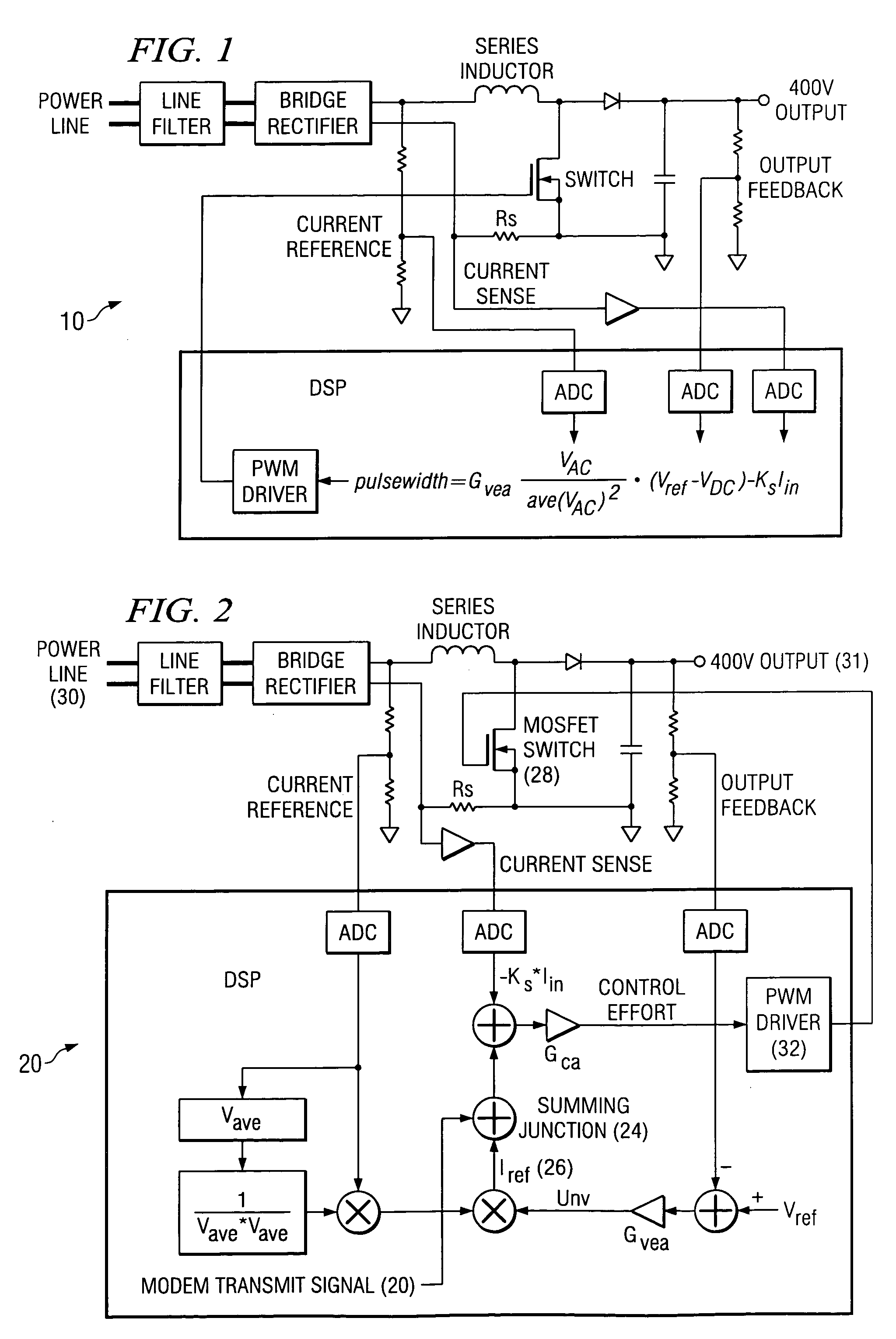
[0012]Referring now to FIG. 2 there is shown a first preferred embodiment of the invention seen to comprise a PFC controller at 20. The PFC circuit 20 controls the current drawn from the power line so that the current follows a sine wave that is in phase with the 60 Hz line voltage. In this way a power factor value near 1.0 can be achieved. To calculate the control effort, the input power line voltage is measured and normalized by dividing by the average input voltage. This forms a reference for the controlled line current. The reference signal is further modified by adjusting it's amplitude based on the measured output voltage 31. The current is made to follow this reference voltage by comparing the measured current with the reference and using the resulting error to define the pulse width modulator (PWM) 32 duty cycle that drives the power MOSFET 28. By modifying this control effort a PLC transmit waveform, constructed in a microprocessor or DSP, can be added at 24 to the current ...


PUM


Abstract

A PFC circuit modulating a power line using pulse width modulation (PWM) to drive a power MOSFET and series inductor across the power line. Since many modern electronic systems include a power factor correction circuit (PFC) that already includes a series inductor and power MOSFET, a PLC is incorporated into a controller to inject a PLC transmit signal into a control loop for the PFC circuit. This can be done using either an analog PFC controller, such as the UCC28517, the UCC2819A, or a digital PFC controller such as based on a TMS320C24xx DSP.

Description

FIELD OF THE INVENTION[0001]The present invention is generally related to power line communication (PLC), and more particularly to electronic systems having power factor correction (PFC).BACKGROUND OF THE INVENTION[0002]For power line communication (PLC) signals to pass through a conventional distribution transformer they need to be below about 3 kHz. By using the frequency band between 1 kHz and 3 kHz a communication channel can be established for which the range of the PLC signal is not limited by the distribution transformers. However, compared to PLC systems using higher frequencies (such as 132 kHz), the components needed to capacitively couple or transformer couple the PLC signal to the power line become prohibitively large.[0003]Many modern electronic systems incorporate a power factor correction (PFC) circuit as part of the function of the power supply circuits. The PFC circuit's job is to generate the bulk voltage for rest of the system, and to shape the current waveform so...

Claims


Application Information

Patent Timeline
Patent Type & Authority Patents(United States)
IPC IPC(8): G05F1/00H02M5/45
CPCG05F1/70H02M1/42H04B3/544H04L25/4902H04B2201/70706H04B2203/5416H04B2203/5483H04B2203/5491H04L27/2602Y02B70/12Y02B70/10H04L27/26025
Inventor HAGEN, MARK DAVIDJANSEN, ROBERT E.
Owner TEXAS INSTR INC
Why Eureka
Try Eureka