Beam axle with integral sensor mount and target

a technology of beam axle and sensor mount, which is applied in the field of beam axle with integral sensor mount and target, axle assembly, etc., can solve the problem that the beam axle is not susceptible to improvement, and achieves the effect of improving the accuracy of the beam axl

Active Publication Date: 2007-04-17
AMERICAN AXLE & MFG
View PDF22 Cites 11 Cited by
  • Summary
  • Abstract
  • Description
  • Claims
  • Application Information

AI Technical Summary

Problems solved by technology

While such arrangements are suited for their intended purpose, they are nonetheless susceptible to improvement.

Method used


Image

  • Beam axle with integral sensor mount and target
  • Beam axle with integral sensor mount and target
  • Beam axle with integral sensor mount and target

Examples


Embodiment Construction

[0016]The following description of the preferred embodiment is merely exemplary in nature and is in no way intended to limit the invention, its application, or uses.

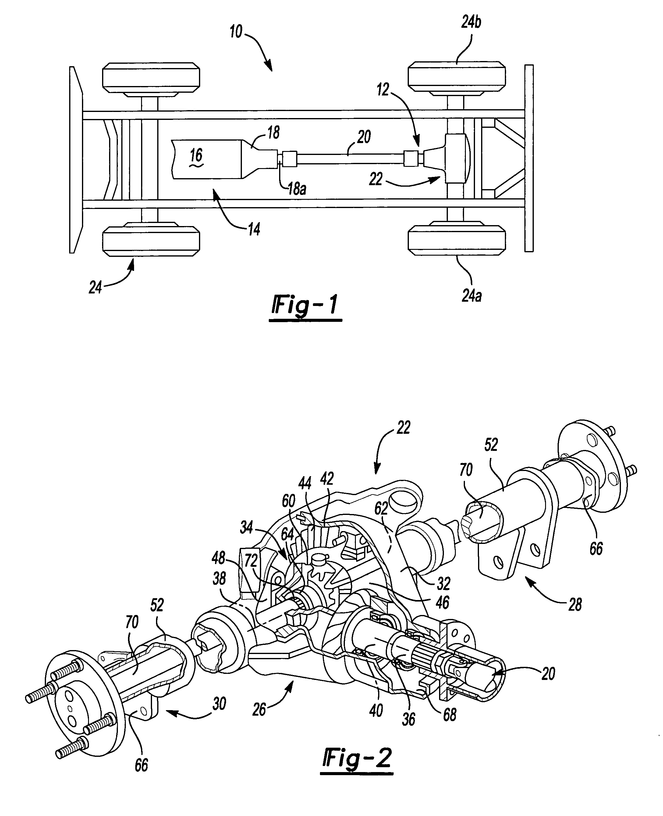
[0017]With reference to FIG. 1 of the drawings, a vehicle having an axle assembly that is constructed in accordance with the teachings of the present invention is generally indicated by reference numeral 10. The vehicle 10 includes a driveline 12 drivable via a connection to a power train 14. The power train 14 includes an engine 16 and a transmission 18. The driveline 12 includes a propshaft assembly 20, a rear axle assembly 22 and a plurality of wheels 24. The engine 16 is mounted in an in-line or longitudinal orientation along the axis of the vehicle 10 and its output is selectively coupled via a conventional clutch to the input of the transmission 18 to transmit rotary power (i.e., drive torque) therebetween. The input of the transmission 18 is commonly aligned with the output of the engine 16 for rotation about a ro...


PUM


Abstract

A vehicle axle assembly having an axle housing, an axle shaft and a sensor. The axle housing has a tubular portion. A flat is formed on an annular wall of the tubular portion proximate a distal end of the tubular portion. A hole, which intersects the flat, is formed through the tubular portion. The axle shaft can have an integrally formed target portion that includes a plurality of teeth. The sensor is mounted in the hole and abuts the flat to space a tip of the sensor apart from the teeth of the target portion by a predetermined distance.

Description

CROSS-REFERENCE TO RELATED APPLICATIONS[0001]This application claims the benefit of U.S. Provisional Patent Application Ser. No. 60 / 555,192 filed Mar. 22, 2004.FIELD OF THE INVENTION[0002]The present invention generally relates to vehicle axles and more particularly to an axle assembly that may include an axle housing with an integral mount for a wheel speed sensor and an axle shaft with an integral sensor target or exciter ring.BACKGROUND OF THE INVENTION[0003]Modern vehicles typically include an axle assembly having a housing and a differential assembly. The housing includes a cavity into which the differential assembly is positioned. The differential assembly is rotatably supported by the housing within the cavity. The differential assembly is mechanically coupled to the vehicle engine by a drive shaft. The differential assembly is also coupled to the vehicle drive wheels via a pair of axle shafts. The differential assembly regulates drive torque between the axle shafts, thereby ...

Claims


Application Information

Patent Timeline
Patent Type & Authority Patents(United States)
IPC IPC(8): G01P3/48F16C32/00G01B7/30B60B35/00B60B35/16B60G17/019B60K17/16F16C1/00G01P1/02G01P3/488
CPCB60B35/121B60B35/16B60G17/019G01P1/026B60B2310/2082B60B2310/224B60G2204/115B60G2206/50B60G2400/208B60G2401/172B60K17/16B60W2520/28B60K17/22
Inventor SWANSON, BLAIR J.
Owner AMERICAN AXLE & MFG
Why Eureka
Try Eureka