
Transducer bracket

a technology for transducers and mounting brackets, applied in the direction of auxiliaries, propulsive elements, sound producing devices, etc., to achieve the effect of simplifying packaging and marketing challenges

Active Publication Date: 2005-05-31
GARMIN
View PDF20 Cites 39 Cited by
  • Summary
  • Abstract
  • Description
  • Claims
  • Application Information

AI Technical Summary

Benefits of technology

[0008]The transom attachment is preferably not a solid planar surface, but is rather defined by the forward edges of the walls around an opening between the walls. In this manner, the mounting body is generally hollow. Such construction reduces the weight and cost of the bracket to and makes it easier to manufacture, as well as cheaper and easier to package and ship. Alternatively, the mounting body may include a substantially solid planar front wall which defines the transom attachment.
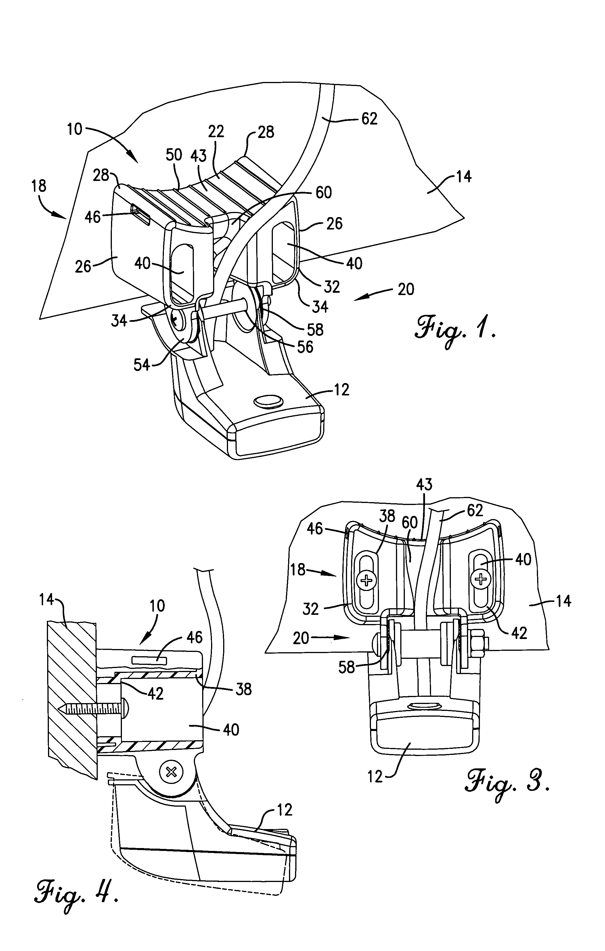
[0012]In the preferred embodiment, the transducer attachment includes two transducer mounting shelfs. Each shelf preferably extends downwardly from and substantially perpendicular to the bottom wall of the mounting body. Each shelf preferably includes a mounting hole surrounded by a plurality of transducer orientation teeth. The mounting holes receive a bolt, or other threaded fastener, in order to secure the transducer to the transducer attachment. The teeth are substantially centered on the corresponding mounting hole and arranged radially thereon. The teeth allow the transducer to be secured at any one of a plurality of angles with respect to the mounting body.
[0013]A channel may be formed between the top and bottom walls of the mounting body for guiding a transducer cable from between the shelfs to above the bracket. The channel preferably extends through the bottom wall between the shelfs to a front or rear edge of the top wall. In this manner, the bracket accommodates the cable while preventing the cable from interfering with adjustment of the angle between the transducer and the bracket.
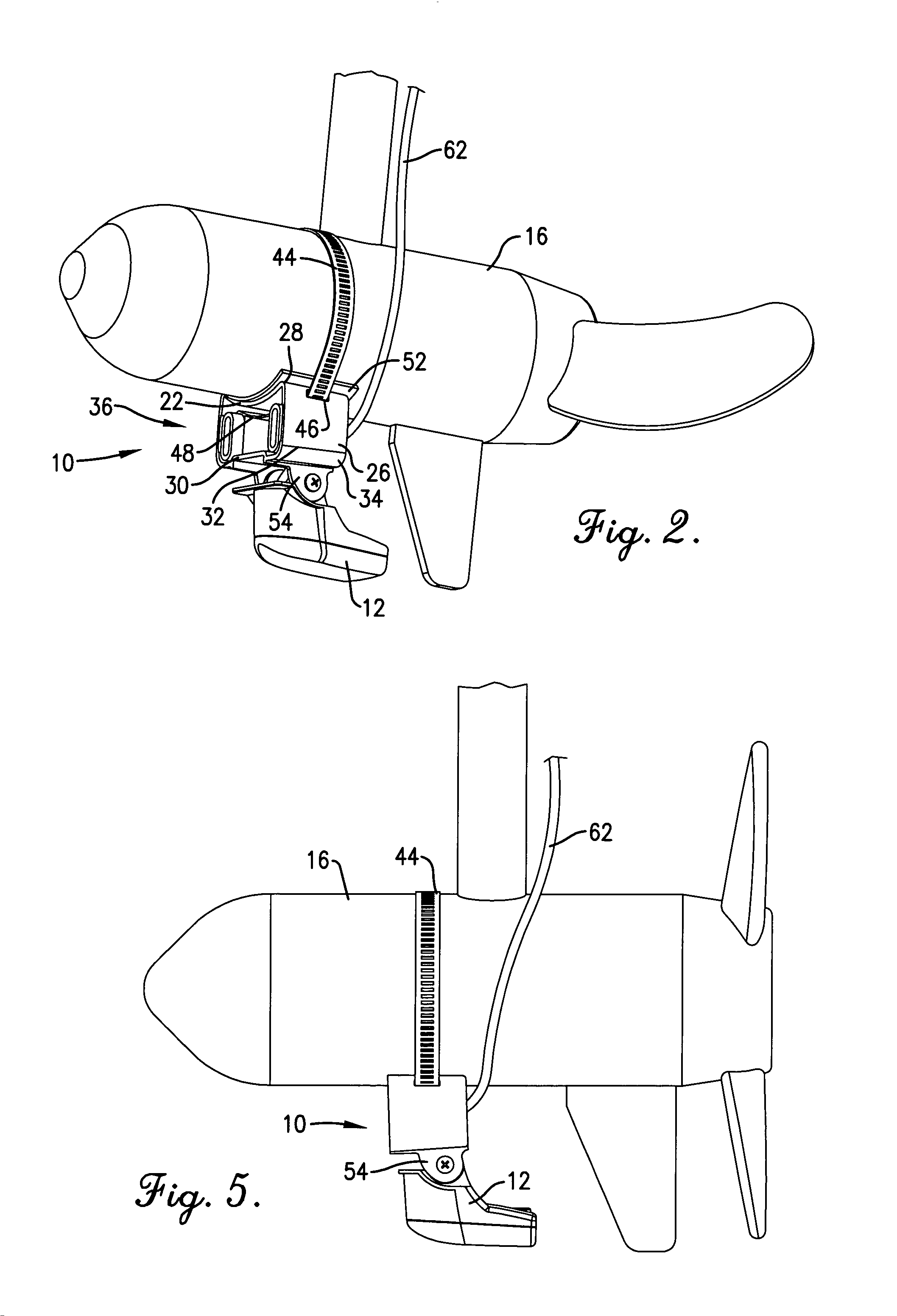
[0017]It can be seen that the bracket of the present invention allows the transducer to be mounted to either the transom or the trolling motor. Thus, only the bracket of the present invention need be packaged and sold with the transducer, thereby simplifying packaging and marketing challenges. For example, packages need not be individually labeled to indicate that they include a transom bracket or a trolling motor bracket.

Problems solved by technology

However, these two surfaces are significantly different, and therefore currently require two different brackets.

Method used


Image

  • Transducer bracket
  • Transducer bracket
  • Transducer bracket

Examples


Embodiment Construction

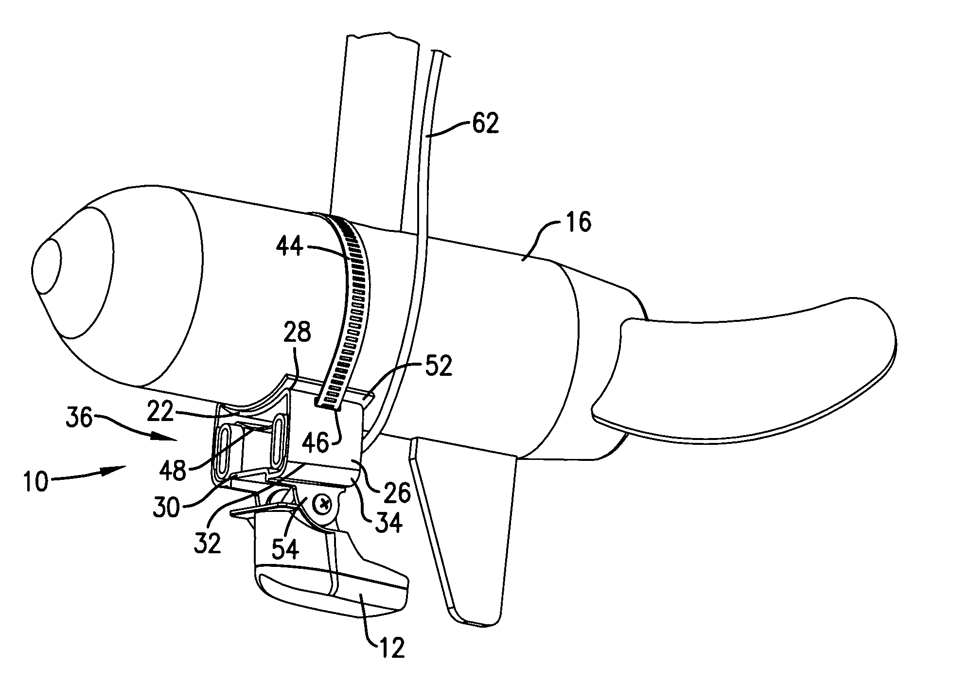
[0024]Referring to the figures, and particularly FIGS. 1 and 2, the preferred universal transducer mounting bracket 10 constructed in accordance with a preferred embodiment of the present invention is illustrated securing an ultrasonic transducer 12 to a transom 14 of a boat or a tolling motor 16. The bracket 10 broadly comprises a mounting body 18, which includes a transom attachment for mating to the transom 14 and a trolling attachment for mating to the trolling motor 16; and a transducer attachment 20 for mating to the transducer 12.

[0025]In the preferred embodiment, the mounting body 18 includes an arcuate top wall 22, two substantially vertical side walls 26 adjacent opposing edges 28 of the top wall 22 and extending downward therefrom, a substantially horizontal bottom wall 30 offset from the top wall 22 and disposed substantially midway between opposing bottom edges 32 of the side walls 26, and two transition walls 34 connecting the side walls 26 to the bottom wall 30. The b...


PUM


Abstract

A universal transducer mounting bracket (10) that may be used to mount a transducer (12) to either a transom (14) or a trolling motor (16). A mounting body (18) broadly comprises a transom attachment (36) for mating to the transom (14), at least one hole (20) through the transom attachment (36) for accepting one or more fasteners therethrough in order to secure the bracket (10) to the transom (14), and an arcuate top wall (22) for mating to the trolling motor (16). The mounting body (18) preferably further includes two side walls (26) and a bottom wall (30) forming the transom attachment (36) for rigidly securing the bracket (10) to the transom (14). The transom attachment (36) may be defined by the walls (22,26,30,34) forming a perimeter around an opening, thereby making the bracket (10) hollow.

Description

BACKGROUND OF THE INVENTION[0001]1. Field of the Invention[0002]The present invention relates to transducer mounting brackets. More particularly, the present invention relates to a universal transducer mounting bracket that may be used to mount a transducer to either a transom of a boat or a trolling motor.[0003]2. Description of Prior Art[0004]Fish finders or depth finders are commonly used by fishermen and other boaters to determine the depth of a body of water and / or the presence of underwater objects, such as fish, corral, etc. Fish finders and depth finders are often not installed in boats during manufacture, and therefore must be installed after purchase.[0005]Fish finders and depth finders include a transducer, which must be secured to an outside portion of a boat. Transducers are commonly secured to either a boat's transom or trolling motor with a bracket. However, these two surfaces are significantly different, and therefore currently require two different brackets. Thus, u...

Claims


Application Information

Patent Timeline
IPC IPC(8): B60L11/02B60L50/10B63B43/18B63H20/00B63J99/00G10K11/00
CPCG10K11/006B63J99/00B63B43/18B63H20/007
Inventor KALIS, ROBERT M.HOPPAS, JEREMY B.MEHAN, CRAIG L.
Owner GARMIN
Learn More