Tire pressure monitoring system

a technology of pressure monitoring system and tire, which is applied in the direction of fluid pressure measurement, inflated body pressure measurement, instruments, etc., can solve the problem of more vibration frequency spectrum subject to disturban

Inactive Publication Date: 2007-04-17
HONDA MOTOR CO LTD
View PDF23 Cites 29 Cited by
  • Summary
  • Abstract
  • Description
  • Claims
  • Application Information

AI Technical Summary

Benefits of technology

[0015]With this construction of the tire pressure monitoring system, even if the tire is replaced with a different kind of tire, underinflation of the tire can be determined precisely by resetting the former reference spectrum data and preparing new reference spectrum data for the replaced tire.

Problems solved by technology

The wider the contact area, the more the produced vibration frequency spectrum is subject to disturbance.

Method used


Image

  • Tire pressure monitoring system
  • Tire pressure monitoring system
  • Tire pressure monitoring system

Examples


first embodiment

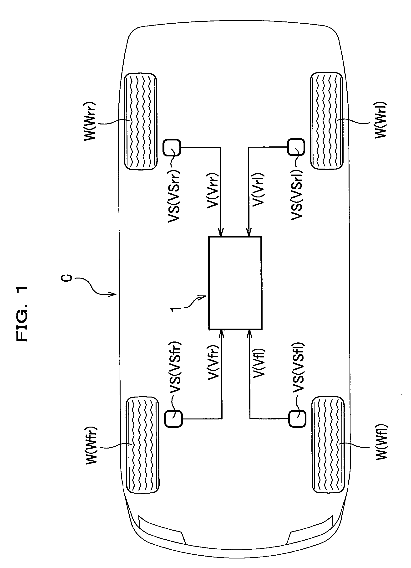
[0029]FIG. 1 schematically illustrates a four-wheeled vehicle onto which is mounted a tire pressure monitoring system according to a

Construction of Tire Pressure Monitoring System

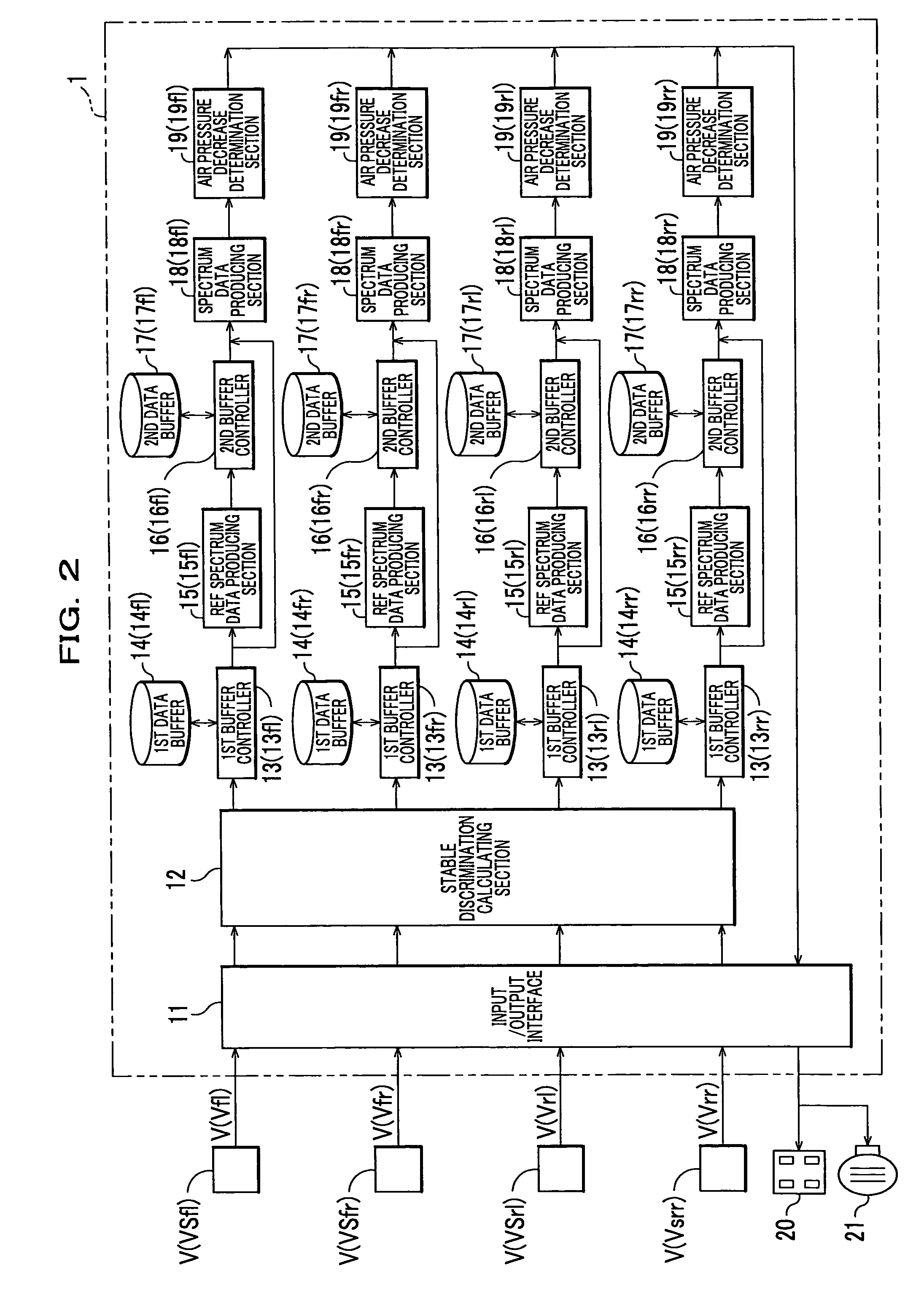
[0030]The construction of a tire pressure monitoring system 1 according to the first embodiment will be described in connection with the construction of a four-wheeled vehicle (hereinafter merely referred to as a “vehicle”) C.

[0031]As shown in FIG. 1, the vehicle C is provided with a wheel speed sensor VS (VSfl, VSfr, VSrl, VSrr) for detecting wheel speed V (Vfl, Vfr, Vrl, Vrr) as wheel vibration detection means at each wheel W (left and right front wheels Wfl, Wfr and left and right rear wheels Wrl, Wrr). Throughout the specification, subscripts attached to a reference numeral, such as fl, fr, rl, and rr indicate front left wheel side, front right wheel side, rear left wheel side, and rear right wheel side, respectively.

[0032]The wheel speed sensor VS is a known wheel sensor which includes, for example, a ...

second embodiment

[0072]To be more specific, the calculation method is based on the findings that detection values of the vibration detection sensor (wheel speed sensor) change due to a level difference or a bump (roughness on the road surface), and that such a change first appears in the detection values at the front wheel sensors and then appears in the detection values at the rear wheel sensors if the vehicle runs in the advance direction In this instance, if the changes in the detections values at the front and rear wheels are derived from the same level difference or bump, and if the time interval between the changes is obtained, vehicle speed can be obtained based on the wheel base (reference distance) of the vehicle without being affected by a change in the tire diameter.

[0073]This calculation method can calculate vehicle speed in consideration of time required for a certain length of object (vehicle body) to pass over a point (a bump, etc.) on the road. In principle, this is different from t...


PUM

PropertyMeasurementUnit
speedaaaaaaaaaa
speedaaaaaaaaaa
speedaaaaaaaaaa

Abstract

A vehicle C is provided with four wheel speed sensors VS (VSfl, VSfr, VSrl, VSrr) (wheel vibration detection means) for detecting wheel speed V (Vfl, Vfr, Vrl, Vrr) at respective four wheels W (left and right front wheels Wfl, Wfr and left and right rear wheels Wrl, Wrr). When the tire pressure is in the normal value, a tire pressure monitoring system 1 prepares vibration frequency reference spectrum data for predetermined vehicle speed bands based on the detection values of each wheel speed sensor VS. The tire pressure monitoring system 1 compares the current vibration frequency spectrum data and the vibration frequency reference spectrum data corresponding to the current vehicle speed band, and determines that the tire is underinflated if the comparison result exceeds a predetermined value.

Description

CROSS-REFERENCE TO RELATED APPLICATIONS[0001]The present application claims priority to Japanese Patent Application No. 2003-174399, the contents of which are hereby incorporated by reference.BACKGROUND OF THE INVENTION[0002]The present invention relates to a tire pressure monitoring system to be mounted, for example, on a vehicle, and particularly to a technique for accurately monitoring tire pressure with a relatively simple structure.[0003]Drivability or maneuvering stability of vehicles greatly depends on air pressure of tires as contacting points with the road surface as well as the structure of suspensions or a steering device. For example, a tire with insufficient air pressure inevitably decreases its rigidity and increases its contact area with the road surface. By this and also due to lack of uniformity (lack of uniformity of the shape), the steering response deteriorates to a greater extent. Because decreased tire pressure results in an increase in temperature of the tire ...

Claims


Application Information

Patent Timeline
Patent Type & Authority Patents(United States)
IPC IPC(8): B60C23/02B60C23/06G01L17/00
CPCB60C23/061B60C23/062
Inventor KIN, KEIYU
Owner HONDA MOTOR CO LTD
Why Eureka
Try Eureka