
Systems and methods for proximity control of a barrier

a technology of proximity control and proximity control, which is applied in the direction of traffic control systems, transmission systems, alarms, etc., can solve the problems of not being convenient or safe for the driver to remove his/her hands, the user may forget to activate the operator to close the barrier, and the use of this technology may be expensiv

Active Publication Date: 2007-04-17
TSUI GALLEN KA LEUNG +1
View PDF56 Cites 51 Cited by
  • Summary
  • Abstract
  • Description
  • Claims
  • Application Information

AI Technical Summary

Benefits of technology

"The patent describes a system and method for controlling the opening and closing of a barrier using a transmitter and a receiver. The transmitter sends a control signal with information about its own identity, direction, and position. The receiver stores a predetermined delay for closing the barrier, as well as user-defined directional and position information. When the receiver receives the control signal, it compares the directional and position information to the user-defined information. If there is a match, the receiver activates the barrier control device once the predetermined delay has passed. This system allows for more precise and efficient control of the barrier, improving safety and convenience for users."

Problems solved by technology

However, there are times that users may forget to activate the operator to close the barrier.
Alternatively, it may not be convenient or safe for the driver to remove his / her hands from the steering wheel to activate the wireless transmitter.
There are however, several disadvantages in using such technology.
Although GPS systems are widely available, it is rather expensive to employ this technology for barrier control operation.
Another disadvantage in implementing GPS technology for such use is accuracy.
Most consumer-grade GPS receivers are accurate to only within 50 feet, which means that an error of up to 50 feet may be expected.
For applications such as garage door control, such a range of error may be unacceptable.
There are other sources of errors such as signal multi-path, orbital errors, Ionosphere and troposphere delays, receiver clock errors etc.

Method used


Image

  • Systems and methods for proximity control of a barrier
  • Systems and methods for proximity control of a barrier
  • Systems and methods for proximity control of a barrier

Examples


Embodiment Construction

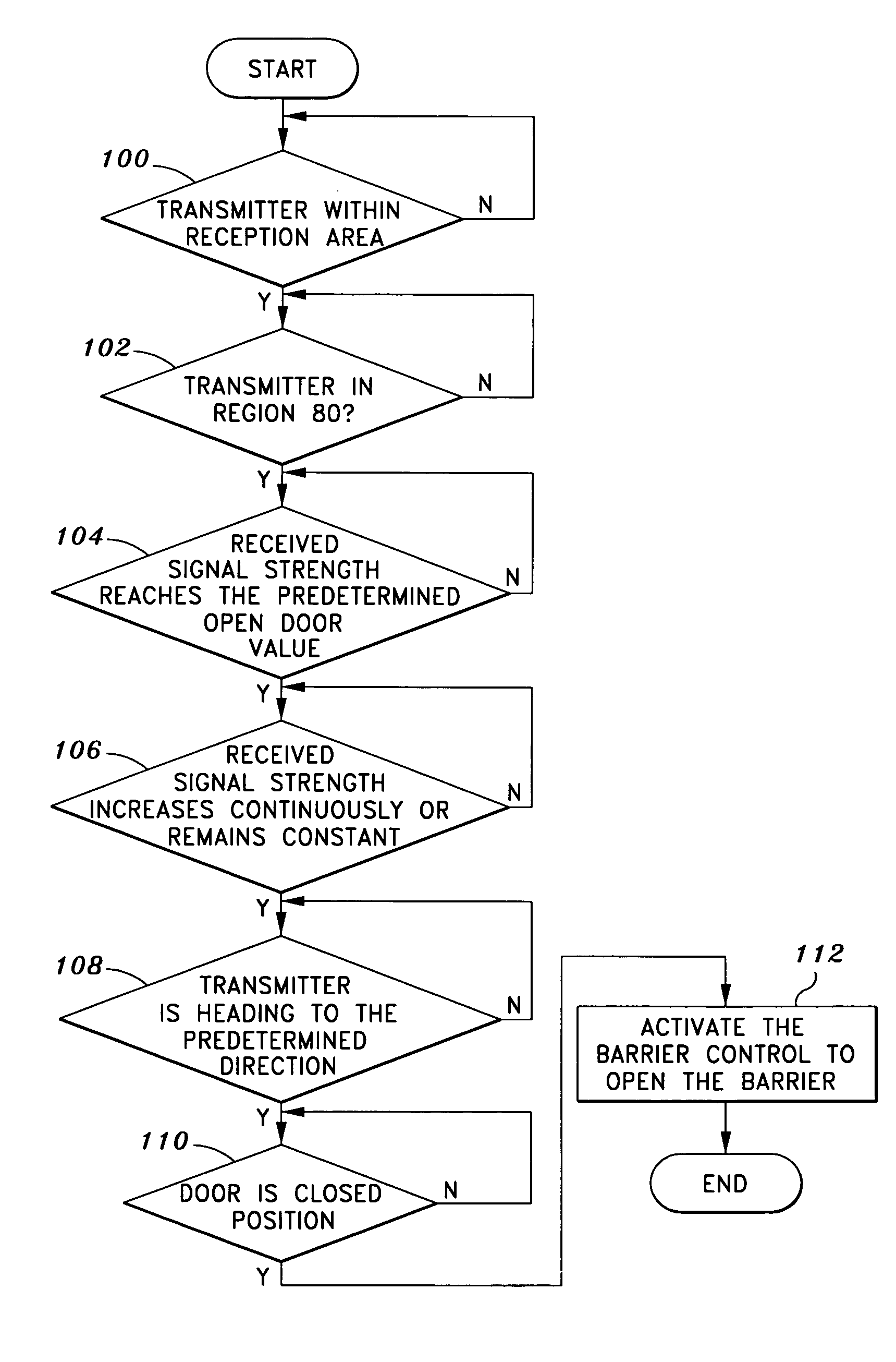
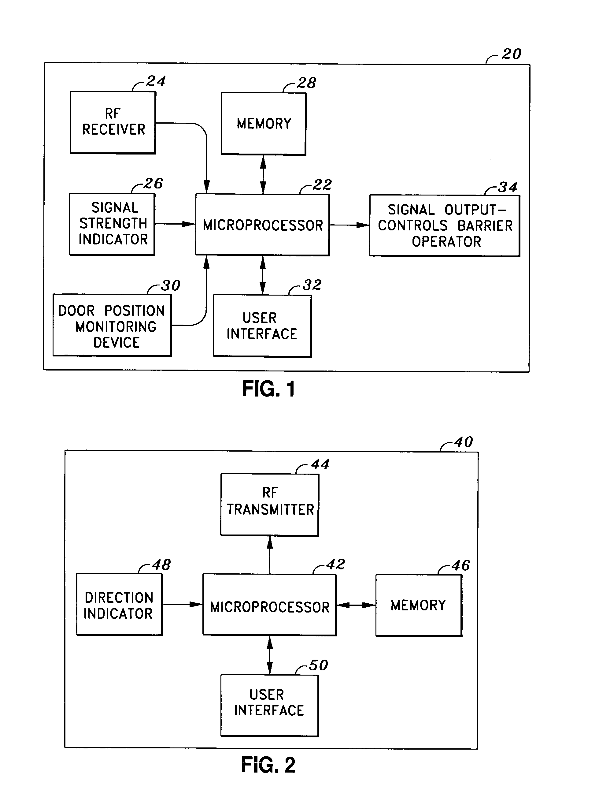
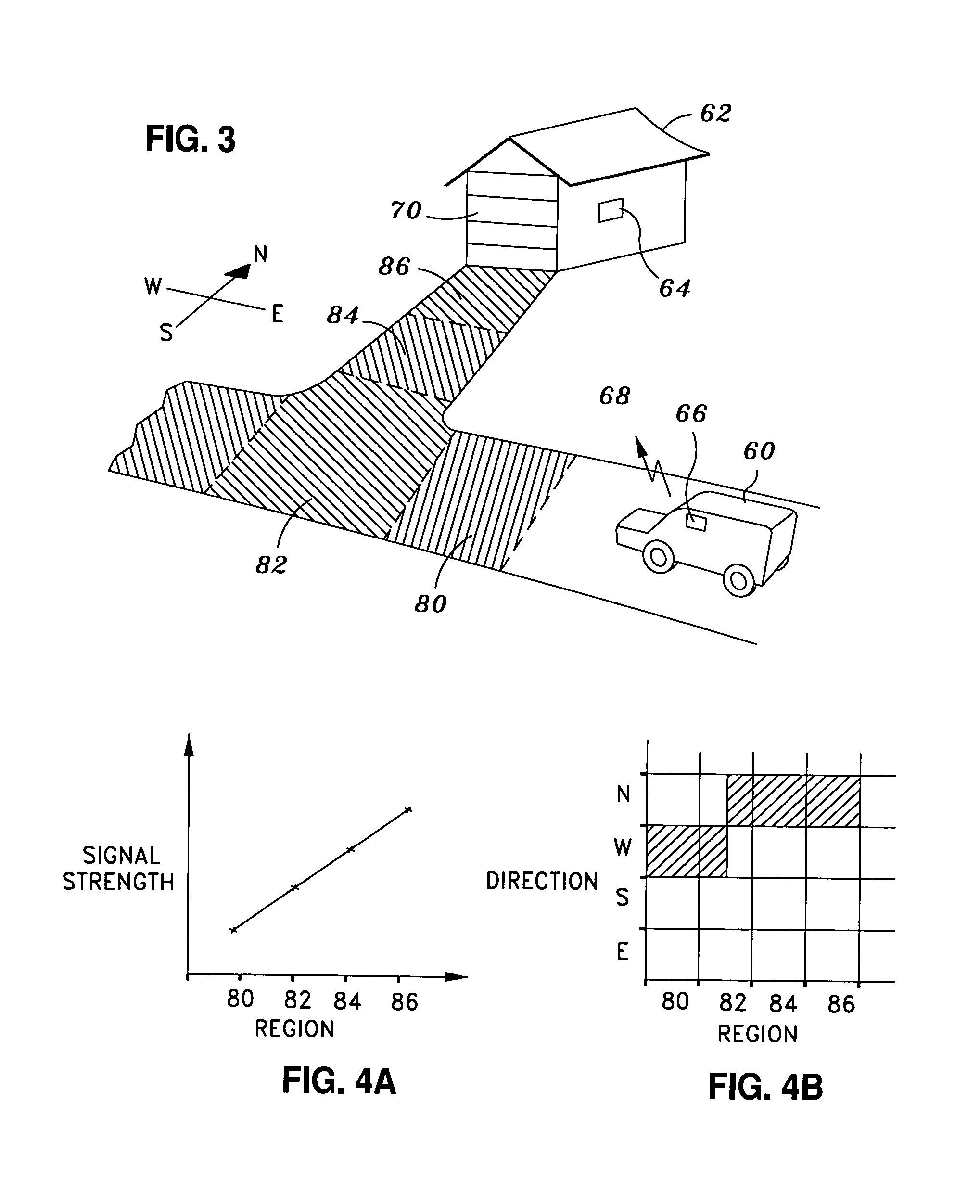
[0018]One aspect of the invention involves a proximity barrier control system that comprises a stationary wireless signal receiving device. The signal receiving device may monitor at least one transmitting device within a predetermined coverage area. Such a receiving device may be a radio frequency receiver located near the barrier. The transmitting device may be a radio frequency transmitter attached to a mobile object, such as a vehicle or person. Since the radio frequency receiver is fixed at one location, in one embodiment the only time that the receiver receives signals from the transmitter is when the transmitter is within the reception range. In one embodiment, a barrier control mechanism, to which the receiver may be coupled, actuates the barrier when the transmitter is in close proximity. In yet another embodiment, multiple receiving devices may be used to monitor the position of the transmitting device. The use of multiple receiving devices may reduce the effect of interfe...


PUM


Abstract

A system and method for proximity control of a barrier comprises a stationary wireless signal receiving device and a mobile transmitting device. The wireless signal receiving device may monitor at least one transmitting device within a predetermined coverage area and may be a radio frequency receiver or a spread spectrum receiver located near the barrier. In one embodiment, the transmitter device emits a control signal that is received by the receiving device when the transmitter is within a reception range. In one embodiment, the control signal includes transmitter identification information, directional information and position information. In another embodiment, the barrier is closed only after a predetermined delay has lapsed.

Description

CROSS REFERENCE TO RELATED APPLICATION[0001]This application is a continuation-in-part of U.S. patent application having application Ser. No. 10 / 875,343 filed on Jun. 23, 2004 now U.S. Pat. No. 7,088,265, which claims the benefit of U.S. provisional patent application having application No. 60 / 554,725, filed on Mar. 18, 2004.FIELD OF THE INVENTION [0002]The invention relates in general to systems and methods for proximity control of a barrier. In particular, the proximate location of an object to a barrier is identified, and the barrier is actuated when one or more conditions are met.BACKGROUND [0003]Automatic barrier operators such as a garage door opener or gate opener are used in many homes. These operators typically require the activation of a wireless transmitter in order to open or close the barrier. However, there are times that users may forget to activate the operator to close the barrier. Alternatively, it may not be convenient or safe for the driver to remove his / her hand...

Claims


Application Information

Patent Timeline
Patent Type & Authority Patents(United States)
IPC IPC(8): G08G1/123G07C9/00H04B1/00
CPCG07C9/00182G07C2009/00793G07C2009/00928G07C2209/63
Inventor TSUI, GALLEN KA LEUNGTSUI, PHILIP Y. W.
Owner TSUI GALLEN KA LEUNG
Learn More