

Wireless communication including diversity transmission and reception
a technology of applied in the field of wireless communication including diversity transmission and reception, can solve the problem of not being able to use a part of the reception electric field strength of the reception signal in demodulating processing, and achieve the effect of improving reception quality
- Summary
- Abstract
- Description
- Claims
- Application Information
AI Technical Summary
Benefits of technology
Problems solved by technology
Method used
Image

Examples
embodiment 1
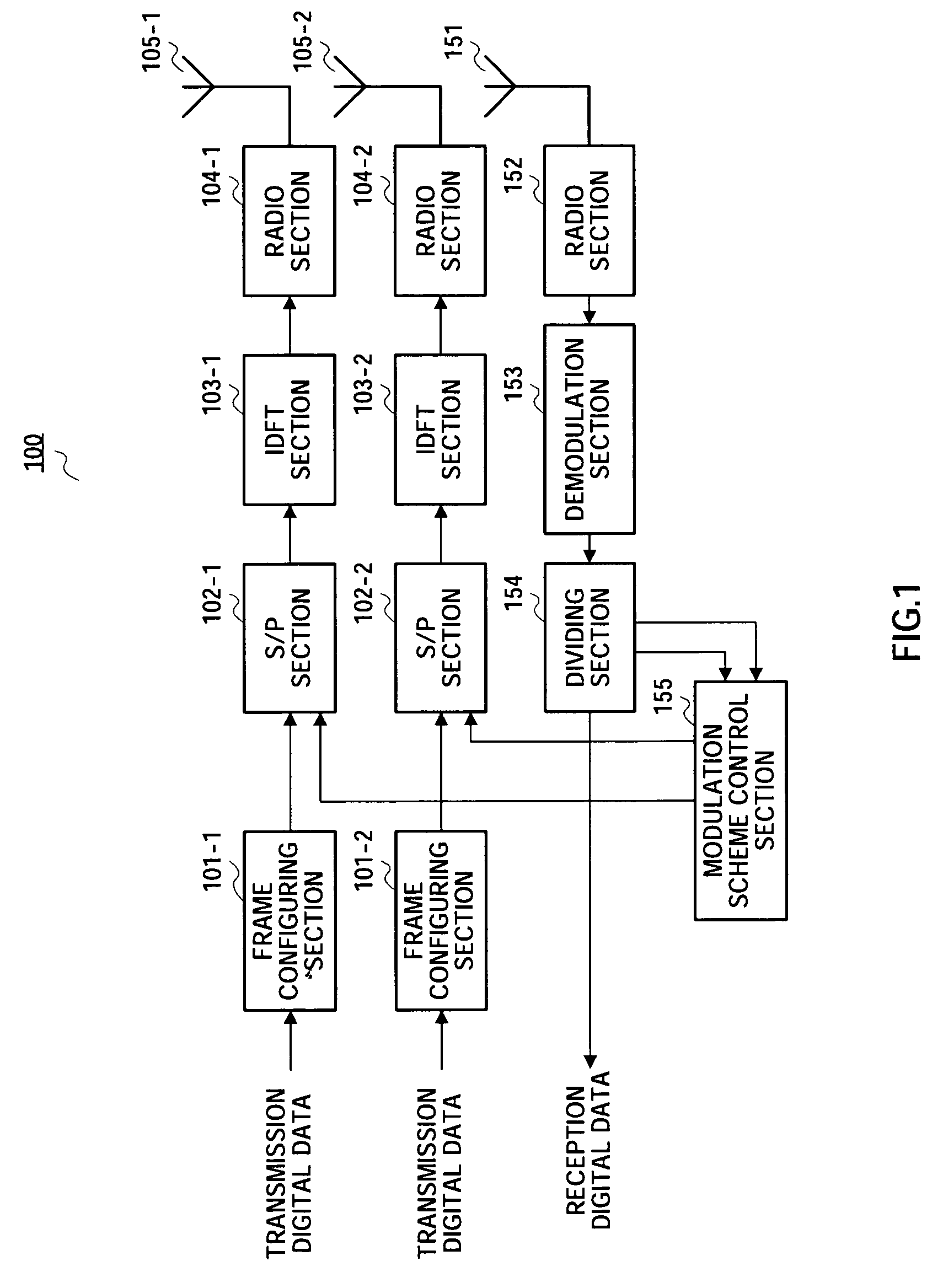
[0055]Embodiment 1 describes the case where in multi-carrier communications using MIMO, a modulation scheme is controlled based on the reception electric field strength of the entire system and effective reception electric field strength.
[0056]FIG. 1 is a block diagram illustrating a configuration of a base station apparatus according to Embodiment 1. In FIG. 1, base station apparatus 100 has, on the transmission side, frame configuring sections 101-1 and 101-2, S / P sections 102-1 and 102-2, IDFT sections 103-1 and 103-2, radio sections 104-1 and 104-2, and transmission antennas 105-1 and 105-2. Further, base station apparatus 100 has, on the reception side, reception antenna 151, radio section 152, demodulation section 153, dividing section 154 and modulation scheme control section 155.
[0057]Each of frame configuring sections 101-1 and 101-2 receives as its input transmission digital data, inserts a channel estimation symbol and guard symbol to the transmission digital data to gene...
embodiment 2
[0095]Embodiment 2 describes the case where in single-carrier communications using MIMO, a modulation scheme is controlled based on the reception electric field strength of the entire system and effective reception electric field strength.
[0096]FIG. 8 is a block diagram illustrating a configuration of a base station apparatus according to Embodiment 2. In addition, in base station apparatus 800 as shown in FIG. 8, structural sections common to base station apparatus 100 as shown in FIG. 1 are assigned the same reference numerals as in FIG. 1 to omit descriptions.
[0097]Base station apparatus 800 as shown in FIG. 8 has the same configuration as that of base station apparatus 100 as shown in FIG. 1 except that S / P sections 102-1 and 102-2 and IDFT sections 103-1 and 103-2 are eliminated and that modulation sections 801-1 and 801-2 and spreading sections 802-1 and 802-2 are added.
[0098]Each of frame configuring sections 101-1 and 101-2 receives as its input transmission digital data, in...
embodiment 3
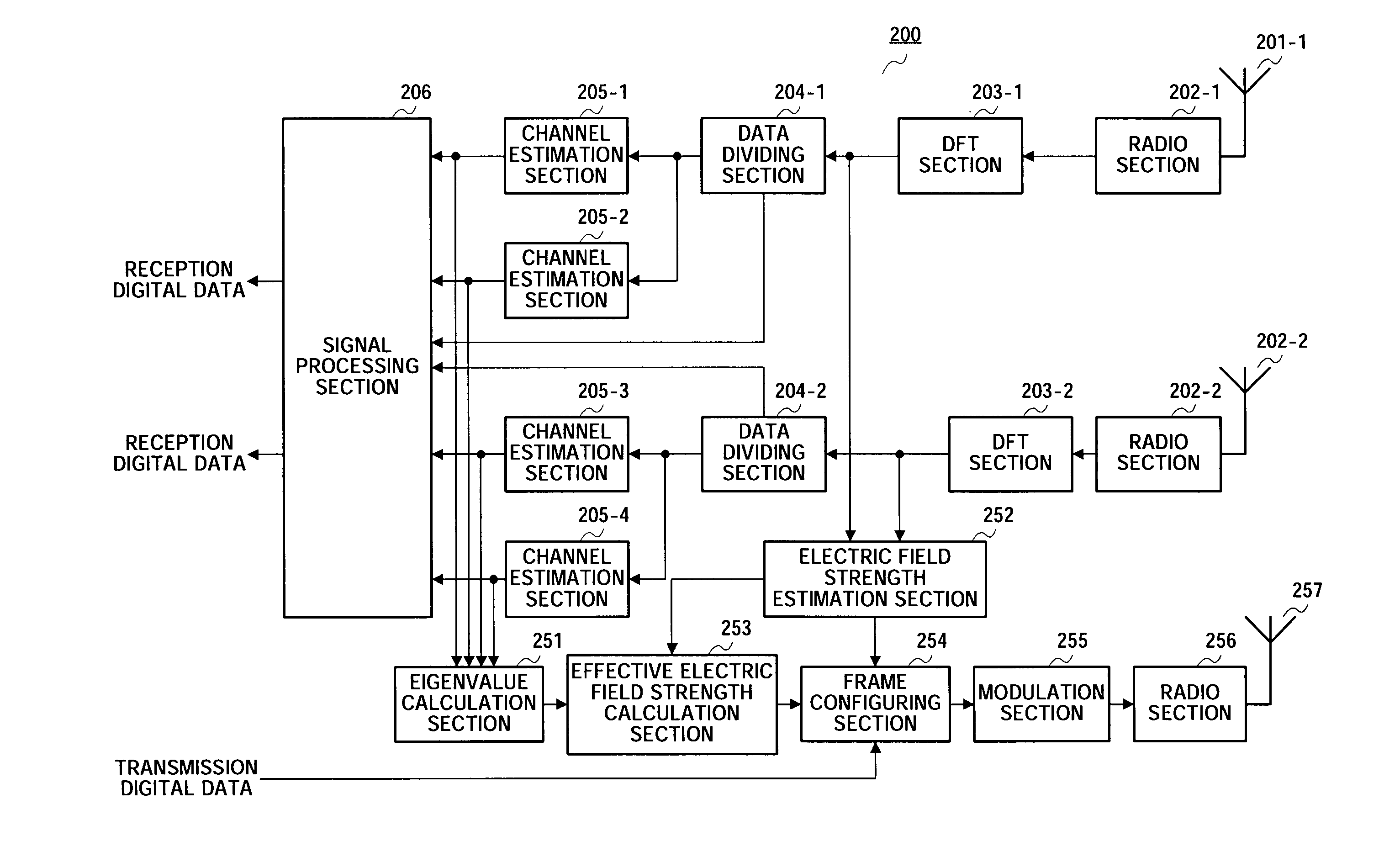
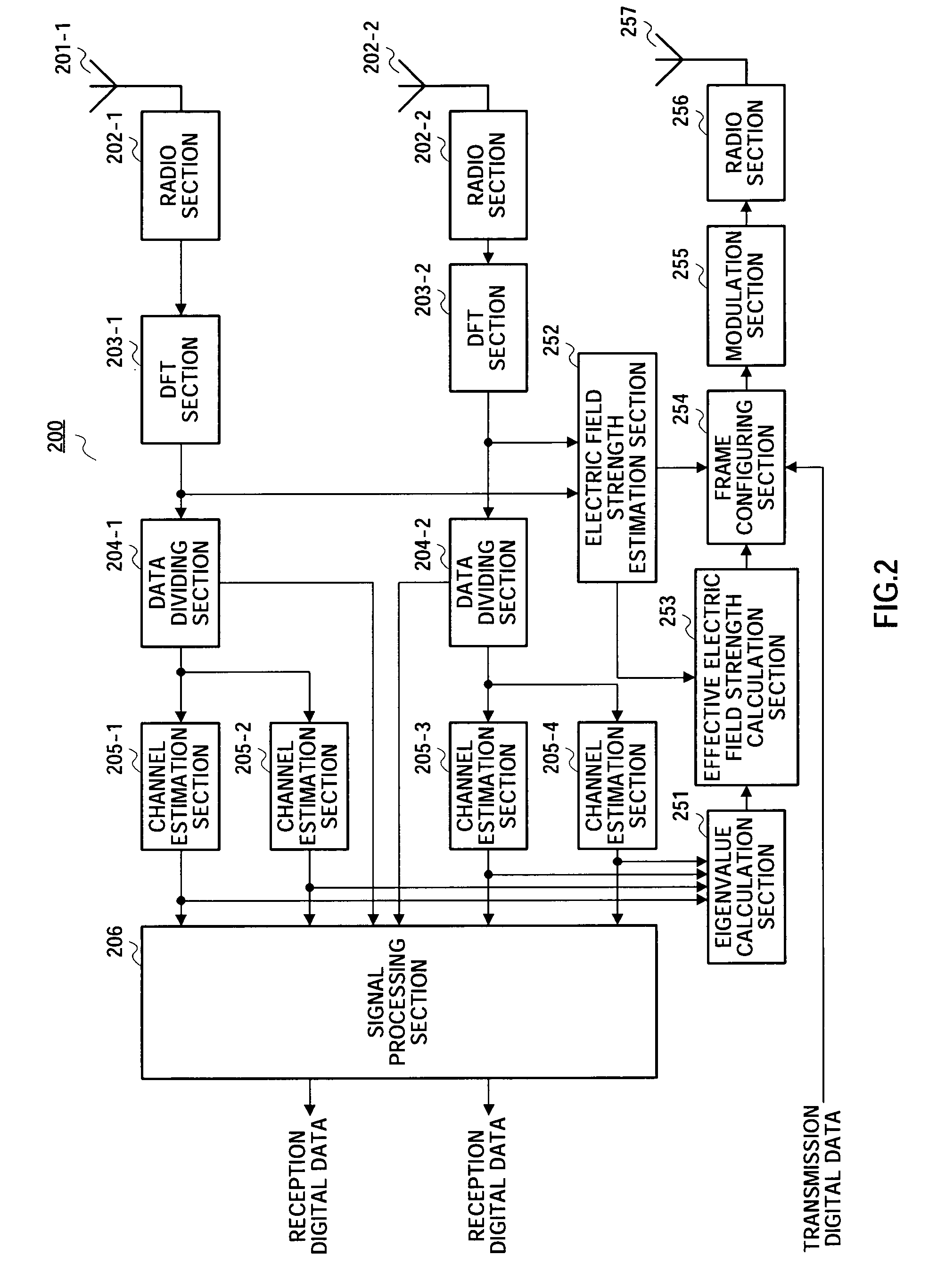
[0109]Embodiment 3 describes the case where in multi-carrier communications using MIMO, transmission antennas are switched based on the reception electric field strength of the entire system and effective reception electric field strength. In addition, a configuration of a communication terminal apparatus of this Embodiment is the same as that of communication terminal apparatus 200 in FIG. 2 as described in Embodiment 1, and descriptions thereof are omitted.
[0110]FIG. 10 is a block diagram illustrating a configuration of a base station apparatus according to Embodiment 3. In addition, in base station apparatus 1000 as shown in FIG. 10, structural sections common to base station apparatus 100 as shown in FIG. 1 are assigned the same reference numerals as in FIG. 1 to omit descriptions.
[0111]Base station apparatus 1000 as shown in FIG. 10 has the same configuration as that of base station apparatus 100 as shown in FIG. 1 except that modulation scheme control section 155 is eliminated...
PUM
 Abstract
Description
Claims
Application Information