Vacuum assisted toilet

a technology of assisted toilets and vacuums, applied in the direction of sewer systems, sewage draining, construction, etc., can solve the problems of inefficient use of vacuum force and increase in intensity of force, and achieve the effect of improving the efficiency of flushing operation

Inactive Publication Date: 2007-04-24
THE AMERICAN TEAM
View PDF38 Cites 25 Cited by
  • Summary
  • Abstract
  • Description
  • Claims
  • Application Information

AI Technical Summary

Benefits of technology

[0011]The vacuum assisted toilet of the present invention can also include a control module for controlling the operation of the toilet components. The control module, for example, can control the opening and closing of the vacuum application valve, the function of the pump and, optionally, the operation of the flap valve. The addition of the control module can further enhance the efficiency of the flushing operation.
[0012]The present invention also teaches a method for providing vacuum pressure to assist in the flushing of a toilet. A flushable toilet system is provided. The system can include a toilet and a passage leading to a waste discharge outlet. A source of vacuum is provided and fluidly connected to the discharge passage. The vacuum source can be closed from communication with the discharge trap so that waste liquid from the toilet will not enter the vacuum source. When the toilet is flushed, the vacuum source is placed in communication with the discharge passage for a desired length of time. The vacuum source can be closed before the waste liquid from the toilet reaches the vacuum source.

Problems solved by technology

Second, designers have applied a vacuum force downstream from the toilet.
The shortcoming of each of these types of vacuum assisted toilets is that the evacuator force of the vacuum is used inefficiently.
When the evacuator force has been applied along the discharge trapway, it has been inefficient in that the force increases in intensity only when the leading edge of the flushed water has passed.

Method used


Image

  • Vacuum assisted toilet
  • Vacuum assisted toilet
  • Vacuum assisted toilet

Examples


Embodiment Construction

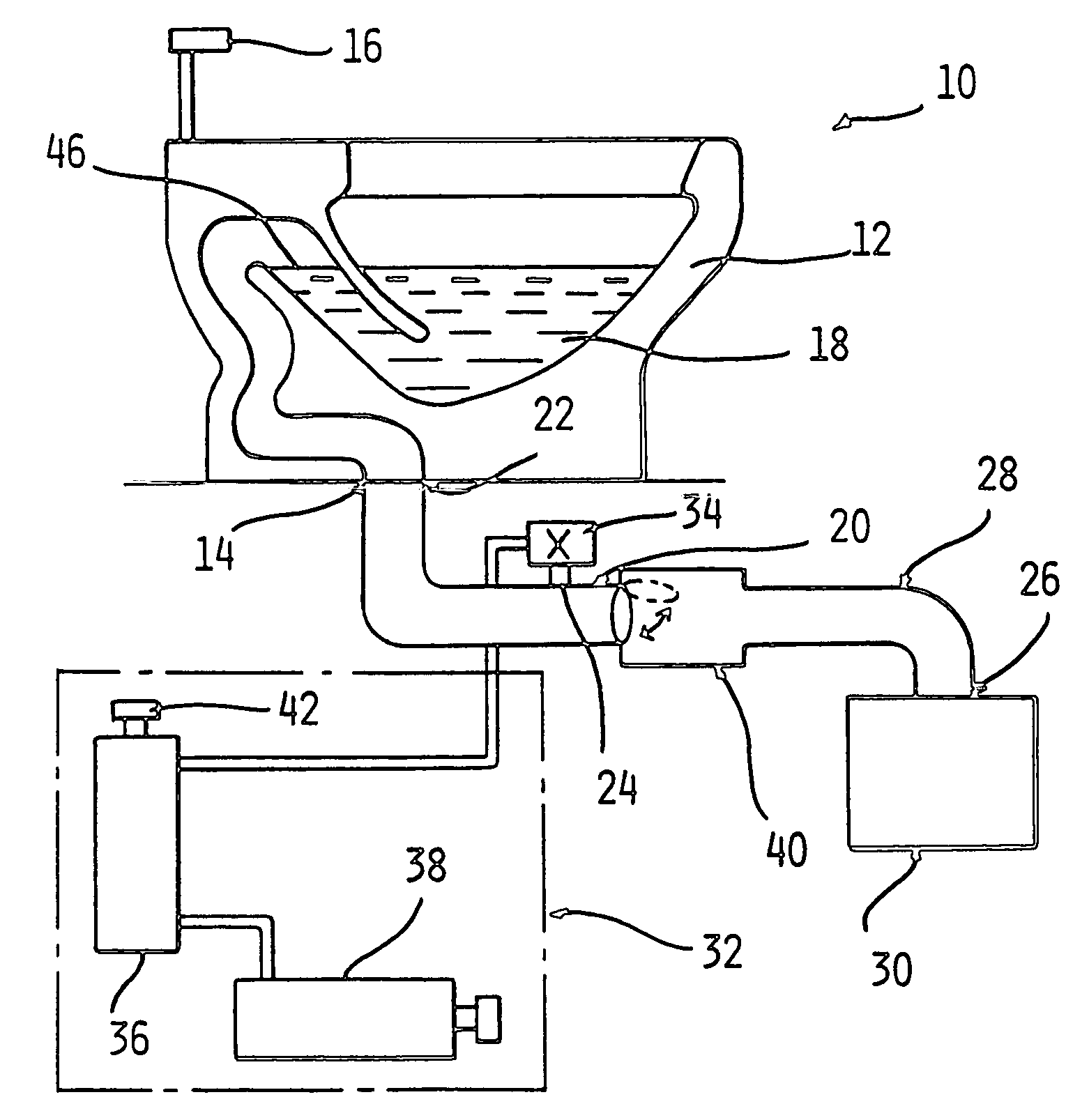
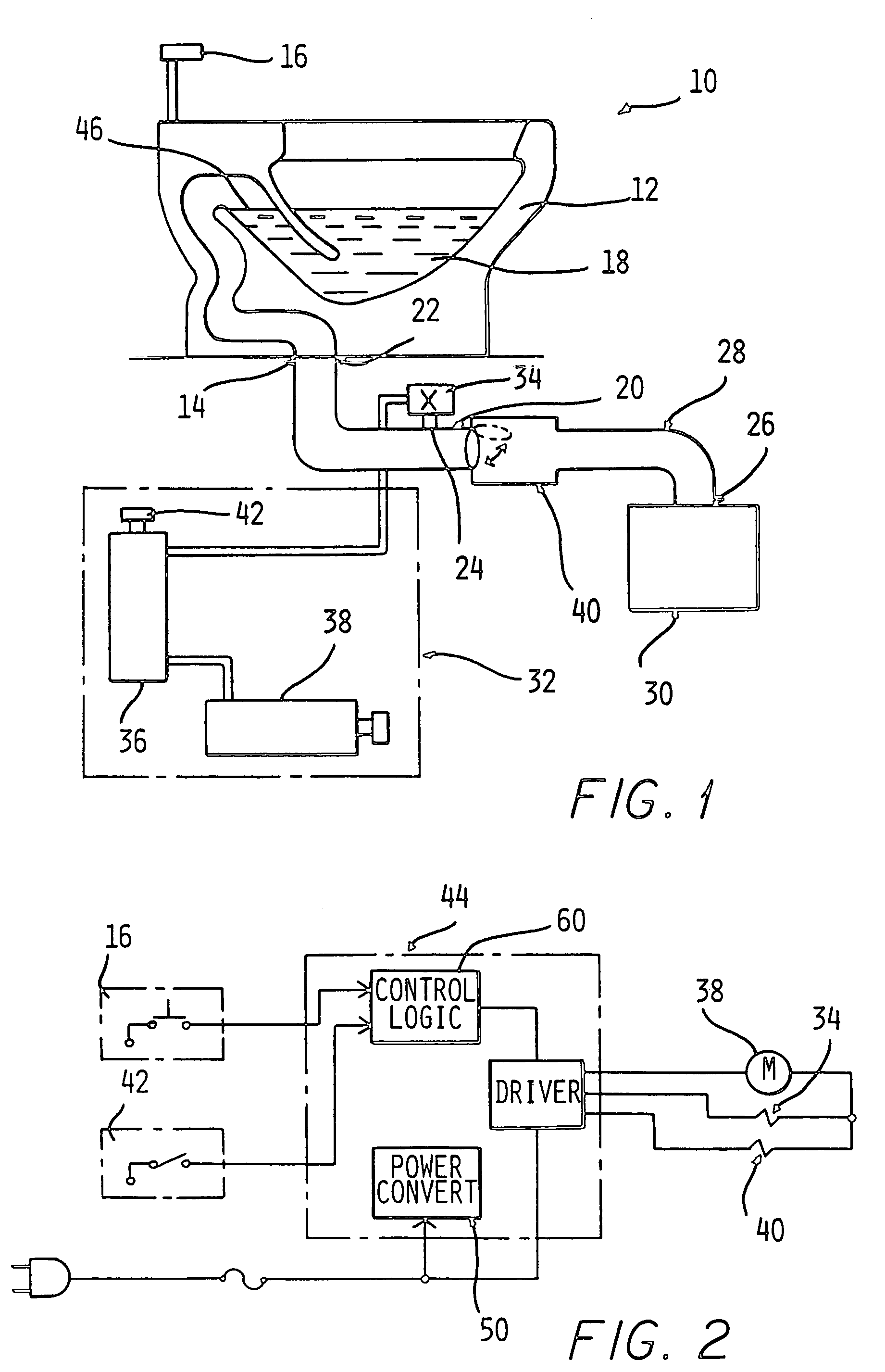
[0017]Referring to FIG. 1, a vacuum assisted toilet 10 of the present invention is depicted. The toilet 10 according to the present invention includes a bowl 12, a discharge port 14 and a flushing actuator 16. The bowl 12 of the toilet 10 is capable of containing a waste water or liquid stream 18. During a flush cycle, the waste stream 18 in the bowl 12 is evacuated through the discharge port 14. The discharge port 14 is fluidly connected to a discharge passage 20. In addition, in a preferred aspect, the discharge passage 20 is a pipe with multiple openings 22 and 24, which joins the toilet 10 to a waste outlet through a discharge pipe 28. Generally, the discharge pipe 28 can be connected at a waste outlet or opening 26 to a holding device 30, by way of example and not limitation, such as a holding tank or septic tank. Alternatively, the discharge pipe 28 can be connected at opening 26 to a sewer line. The discharge passage 20 can include a trap that is essentially a local valley in...


PUM


Abstract

A toilet is provided with a vacuum to assist in the flushing process. The vacuum is provided downstream between the toilet bowl and a waste outlet to draw the waste contents of the toilet bowl and out of the toilet bowl to the waste outlet under pressure. A controllable valve connected to a vacuum source is connected in a discharge passage between the toilet bowl and the waste outlet. The valve is opened to apply vacuum to the discharge passage upon activation of a toilet flush actuator and closes prior to the waste contents of the toilet bowl reaching the location of the valve. A normally closed flap valve is connected between the discharge passage and the waste outlet to define a minimal amount of air in the discharge passage which is removed by the vacuum.

Description

CROSS REFERENCE TO CO-PENDING APPLICATION[0001]This application is a continuation of U.S. patent application Ser. No. 09 / 982,424, filed Oct. 18, 2001 in the name of Karl Blankenburg and entitled “VACUUM ASSIST TOILET”, abandoned, the contents of which are incorporated herein in its entirety.BACKGROUND[0002]This invention relates to a vacuum assisted toilet that uses less water than a conventional toilet. Specifically, the invention refers to a method and apparatus for creating a vacuum downstream of the toilet and upstream of a discharge pipe leading to a sewer pipe or a waste holding tank.[0003]Reducing the amount of water used for each flush has long been a goal of designers of waste removal, or toilet systems. Pursuing this goal has been attempted predominantly in two ways. First, designers have implemented pressurized water holding tanks above the toilet so that water at elevated pressure levels enters the bowl during the flush cycle. Second, designers have applied a vacuum forc...

Claims


Application Information

Patent Timeline
Patent Type & Authority Patents(United States)
IPC IPC(8): E03D11/00
CPCE03F1/006
Inventor BLANKENBURG, KARL
Owner THE AMERICAN TEAM
Why Eureka
Try Eureka