Insulated, high voltage power cable for use with low power signal conductors in conduit

a high-voltage, high-voltage technology, applied in the direction of insulated conductors, cables, conductors, etc., can solve the problems of loss or disruption of signal transmission, serious loss of signal integrity on low-power signal conductors

Active Publication Date: 2007-04-24
ULECTRA CORP
View PDF37 Cites 76 Cited by
  • Summary
  • Abstract
  • Description
  • Claims
  • Application Information

AI Technical Summary

Benefits of technology

[0018]Preferably, the metallic outer jacket comprises a thin, flexible steel jacket. The outer metallic jacket may be spirally wound or may be fabricated of any number of metallic coverings including metal tape, metal foil, flexible metal tubing, braided wires / tapes, parallel wires / tapes and other metallic coverings known to those of skill in the art. The metallic jacket is comprised of a magnetic material or paramagnetic material (such as aluminum) and is grounded. The metallic jacket protects the group of signal conductors from externally induced electromagnetic emissions such as externally induced RF noise up to approximately 1 gigahertz (GHz).
[0019]Thus, in the hybrid cable of the present invention, the signals carried by the one or more groups of signal conductors are protected from both internally and externally generated electromagnetic emissions. The soft magnetic material overlying the power cable power conductors protects, by RF absorption, the one or more groups of signal conductors from electromagnetic emissions emitted by the power conductors due to high voltage, high frequency electrical transients imposed on one or more of the power conductors by external electrical disturbances such as lightening and other high frequency power disturbances.
[0020]Additionally, the grounded outer metallic jacket shields, by electrostatic shielding, the one or more groups of low power signal conductors from electromagnetic emissions generated by external sources in proximity to the hybrid cable. Additionally, the metallic jacket advantageously eliminates the need for metal or plastic conduit when installing the hybrid cable in a commercial or residential building, since the metallic jacket functions as its own metal conduit for building and electrical code purposes.

Problems solved by technology

One problem encountered with running power and data / voice signal conductors in the same conduit is the fill ratio for metal and plastic conduit set forth in the National Electrical Code (N.E.C.).
An even more serious problem encountered with an adjacent arrangement of power conductors and data / voice signal conductors within a section of conduit is that of loss or disruption of signal transmission that would result from external high frequency transients imposed on one or more of the power conductors of the power cable, e.g., a high frequency transient caused by lightening hitting a power line coupled to the power cable.
Because of the proximity of the power cable and the signal conductors disposed in the conduit or raceway, such a high frequency transient traveling along the power cable is likely to interfere with low power signals in proximity to the transient thereby causing a serious loss of signal integrity on the low power signal conductors.

Method used


Image

  • Insulated, high voltage power cable for use with low power signal conductors in conduit
  • Insulated, high voltage power cable for use with low power signal conductors in conduit
  • Insulated, high voltage power cable for use with low power signal conductors in conduit

Examples


first embodiment

[0100]A second preferred embodiment of the hybrid cable of the present invention is shown generally at 10′ in FIGS. 4 and 5. Fundamentally, the hybrid cable 10′ of the second preferred embodiment differs from the hybrid cable 10′ of the first preferred embodiment in that, in the second preferred embodiment, the soft magnetic material 15b′, 17b′, 19b′ is disposed in insulation layers 15a′. 17a′, 19a′ around each of the individual power conductors 14′, 16′, 18′ of the power cable 12′. In the first embodiment, as described above, the soft magnetic material 21a was disposed in a single insulation layer 21 that surrounded all three of the power conductors 14, 16, 18.

second embodiment

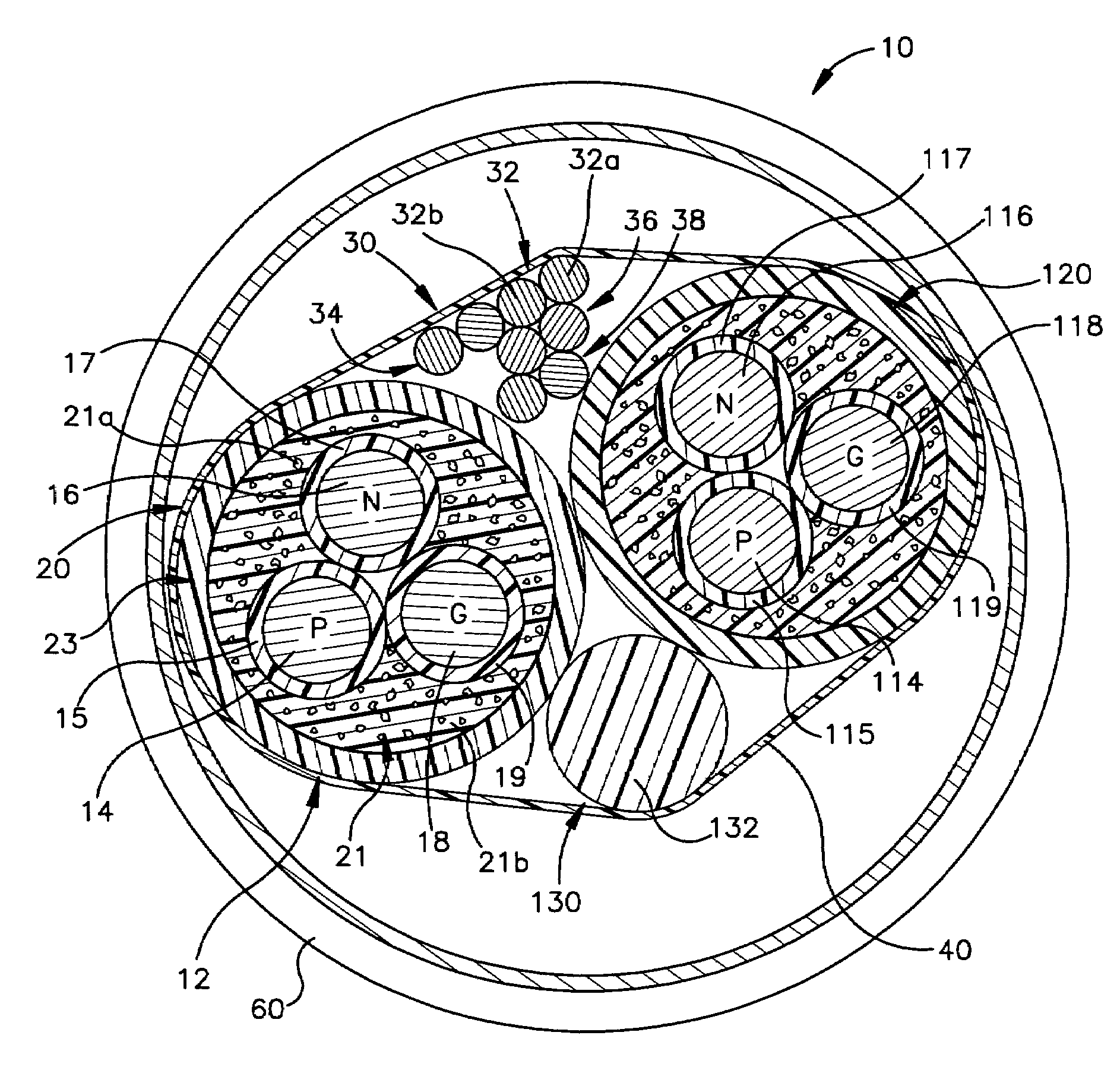
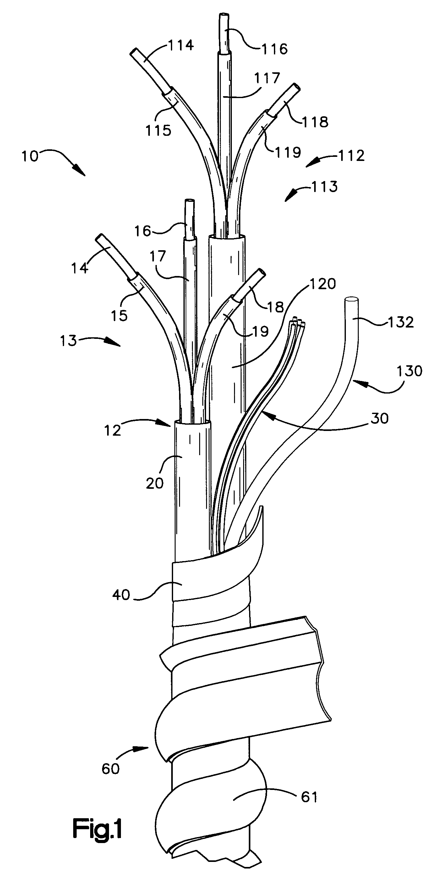
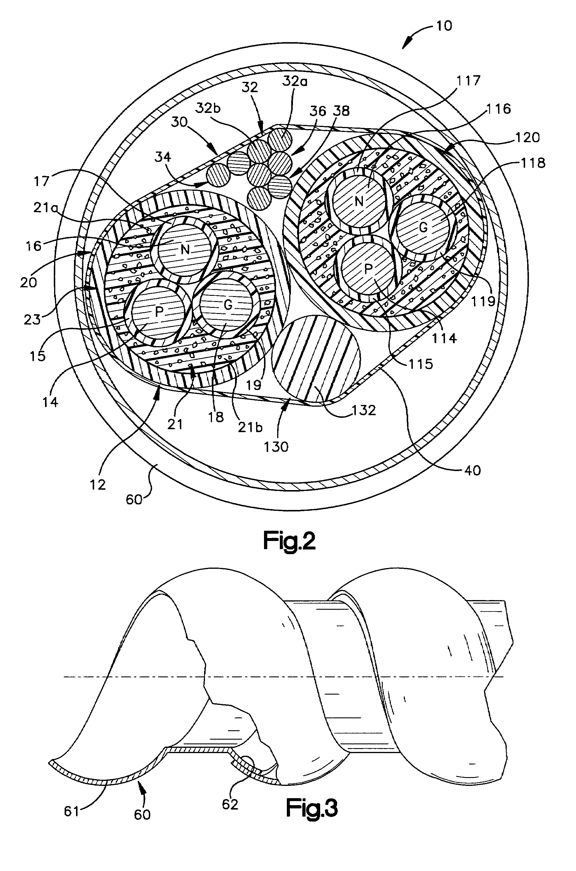
[0101]In the second embodiment, the hybrid cable 10′ includes the power cable 12′ comprising the group of power conductors 13′. The hybrid cable 10′ also includes five groups of data / voice conductors 30′, 130′, 230′, 330′, 430′.

[0102]The group of power conductors 13′ includes the power conductor 14′, the neutral conductor 16′ and the isolated grounding conductor 18′. The power conductors 14′, 16′, 18′ are similar to the power conductors 14, 16, 18 described in the first embodiment. Each of the power conductors 14′, 16′, 18′ includes a respective insulation jacket 15′, 17′, 19′. Each of the power conductor insulation jackets 15′, 17′, 19′ includes an inner layer 15a′, 17a′, 19a′ and an outer layer 15d′, 17d′, 19d′.

[0103]The respective inner layers 15a′, 17a′, 19a′ of the insulation jackets 15′, 17′, 19′ comprise soft magnetic material 15b′, 17b′, 19b′ mixed or interspersed in a binder material 15c′, 17c′, 19c′. The soft magnetic material 15b′, 17b′, 19b′ is similar to the soft magne...


PUM

PropertyMeasurementUnit
coercivityaaaaaaaaaa
power magnitudeaaaaaaaaaa
voltage magnitudeaaaaaaaaaa

Abstract

The present invention is directed to a high voltage, insulated electrical power cable suitable for use adjacent to one or more low power signal communications conductors in metal or plastic conduit or raceway. In one preferred embodiment, the power cable includes a first group of one or more conductors for supplying power and a power conductor insulation jacket enclosing the first group of one or more conductors. The power conductor insulation jacket includes a soft magnetic material that functions as an electromagnetic field shield in the radio frequency range of approximately 1 megahertz to 400 megahertz thereby protecting the integrity of signals transmitted on the adjacent signal communications conductors.

Description

CROSS REFERENCE TO RELATED APPLICATION[0001]The application is a continuation-in-part of U.S. application Ser. No. 10 / 903,756, entitled INTEGRATED POWER AND DATA INSULATED ELECTRICAL CABLE HAVING METALLIC OUTER JACKET, filed on Jul. 30, 2004, now issued as U.S. Pat. No. 6,998,538 on Feb. 14, 2006.FIELD OF THE INVENTION[0002]The present invention is directed to an insulated electrical power cable suitable for use in metal or plastic conduit or raceway in proximity to one or more groups of low power signal conductors and, more particularly, to an insulated electrical power cable including a group of one or more power conductors encased in an insulation jacket including a soft magnetic material which functions to protect the integrity of signals transmitted on the one or more groups of low power signal conductors by absorbing radio frequency (RF) electromagnetic emissions generated by high voltage, high frequency electrical transients which may be present on one or more power conductor...

Claims


Application Information

Patent Timeline
Patent Type & Authority Patents(United States)
IPC IPC(8): H01B11/02
CPCH01B7/225H01B9/003H01B9/02
Inventor FETTEROLF, SR., JAMES R.BLICHASZ, CHARLES S.DONMOYER, WILLIAM L.HEUER, ARTHUR H.PLANAS, SR., ALBERTO E.PLANAS, JR., ALBERTO E.
Owner ULECTRA CORP
Why Eureka
Try Eureka