Optical fiber tape of low polarization mode dispersion characteristic and method for measuring dynamic viscoelasticity of the optical fiber tape
a technology of optical fiber tape and low polarization mode, applied in the field of optical fiber tape, can solve the problems of deterioration of optical, long time per splice, and low demand for optical fiber cables susceptible to little polarization mode dispersion
Inactive Publication Date: 2007-04-24
FURUKAWA ELECTRIC CO LTD
View PDF19 Cites 8 Cited by
- Summary
- Abstract
- Description
- Claims
- Application Information
AI Technical Summary
Benefits of technology
The present invention provides a method for manufacturing and designing optical fiber tapes with low polarization mode dispersion. The method involves measuring the dynamic viscoelasticity of the tape after ultraviolet curing and using an ultraviolet curing resin as the tape bonding material. The resulting optical fiber tape has a maximum level of polarization mode dispersion of 0.3 ps / √km or less. The invention also provides a slot type optical fiber cable that includes the optical fiber tape and a spacer with a slot. The tape bonding material has a loss tangent of not less than 0.60. The optical fiber tape can be used in a dense wavelength division multiplexing system with high signal transmission speed.
Problems solved by technology
Whereas optical fibers should be spliced to each other in architecting a communication system, there are a few kinds of splicing methods for that purpose The fusion splicing method, which excels in reliability and connecting performance among them, has a disadvantage of taking a longer time per splice than other methods.
However, since the deterioration of optical signals by polarization mode dispersion poses a problem in such long distance transmission, especially in a DWDM transmission system, realization of optical fiber cables susceptible to little polarization mode dispersion is in keen demand.
However, there is a problem that, even if optical fibers themselves are superior in polarization mode dispersion, their integration into a tape invites deterioration in polarization mode dispersion.
Also, whereas a tape-shaped optical fiber usually accommodates a plurality of optical fibers, there is a further problem of differences in PMD characteristics among the individual optical fibers.
Thus, in the prevailing state, the polarization mode dispersion of optical fiber tapes has been inadequate especially for use in a DWDM system for long distance transmission.
Method used
View moreImage
Smart ImageViewing Examples

Examples
example 1
[0077]This is an optical fiber tape using resin A as the tape bonding material and dispersion shift optical fibers as the optical fibers.
example 2
[0078]This is an optical fiber tape using resin B as the tape bonding material and dispersion shift optical fibers as the optical fibers.
example 3
[0079]This is an optical fiber tape using resin C as the tape bonding material and dispersion shift optical fibers as the optical fibers.
Login to View More PUM
| Property | Measurement | Unit |
|---|---|---|
| diameter | aaaaa | aaaaa |
| length | aaaaa | aaaaa |
| temperature | aaaaa | aaaaa |
Abstract
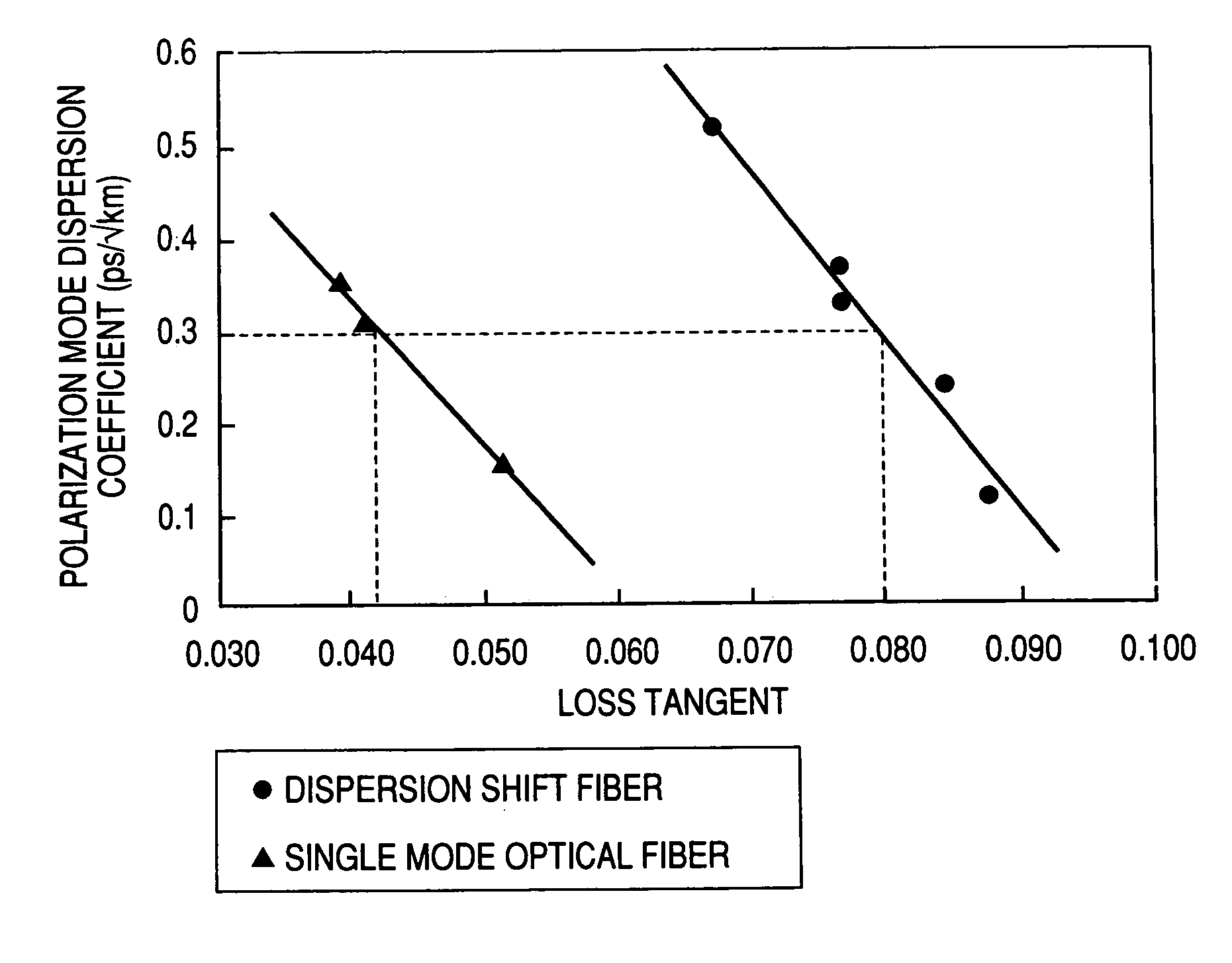
An optical fiber tape having low polarization mode dispersion characteristics and applied to a dense wavelength multiplex (DWDM) transmission system of a transmission rate from several Gb / s to several tens of Gb / S. We have found out that the polarization mode dispersion of an optical fiber tape relates to the loss tangent (tan δ) determined when the dynamic viscoelasticity is measured, and that particularly, if the loss tangent of when a dispersion shift fiber is used is made 0.080 or more and the loss tangent of when a single mode optical fiber is used is made 0.042 or more, the polarization mode coefficient of dispersion (PMD) is reduced to 0.3 ps / √km preferable to realize a DWDM transmission system.
Description
TECHNICAL FIELD[0001]The present invention relates to an optical fiber tape composed of a plurality of optical fibers integrated into a tape form. More particularly, the invention relates to an optical fiber tape for use in high speed transmission, ranging in transmission speed from several Gb / s to several tans of Gb / s.BACKGROUND ART[0002]Along with the rapidly spreading use of the Internet and the expansion of business communication networks, the demand for communication is dramatically increasing with the consequence that the capacities of relayed networks are falling short of the requirement. In this connection, optical fiber networks are pressed for further increases in speed and capacity.[0003]A transmission technique known as dense wavelength division multiplex (hereinafter abbreviated to DWDM), which allows an optical fiber to propagate many wavelengths, is attracting note and coming into growing use as a technique that makes possible a big leap in the expansion of transmissi...
Claims
Login to View More Application Information
Patent Timeline
 Patent Type & Authority Patents(United States)
IPC IPC(8): G02B6/44G01N3/00H04B10/2581
CPCG02B6/4403G01N2203/0094G02B6/02285G02B6/4407
Inventor TANAKA, HIROKINAKAJIMA, YASUOOKADA, MITSUNORITAKAISHI, NORIMITSUMIZOGUCHI, KENICHIYASUI, HIDETOSHI
Owner FURUKAWA ELECTRIC CO LTD
Features
- R&D
- Intellectual Property
- Life Sciences
- Materials
- Tech Scout
- Unparalleled Data Quality
- Higher Quality Content
- 60% Fewer Hallucinations
Learn More Browse by: Latest US Patents, China's latest patents, Technical Efficacy Thesaurus, Application Domain, Technology Topic, Popular Technical Reports.
© 2025 PatSnap. All rights reserved.Legal|Privacy policy|Modern Slavery Act Transparency Statement|Sitemap|About US| Contact US: help@patsnap.com