Vacuum cleaner having a slanted pedestal

a vacuum cleaner and pedestal technology, applied in the field of vacuum cleaners, can solve the problems of creating inconvenience for users further down the line, and achieve the effect of enhancing durability and reliability of the swivel caster

Inactive Publication Date: 2007-05-01
PANASONIC CORP
View PDF10 Cites 25 Cited by
  • Summary
  • Abstract
  • Description
  • Claims
  • Application Information

AI Technical Summary

Benefits of technology

[0007]It is, therefore, a primary object of the present invention to provide a vacuum cleaner capable of enhancing durability and reliability of a swivel caster employed therein.
[0008]It is, therefore, another object of the present invention to provide a vacuum cleaner employing a dust chamber capable of facilitating detachability thereof.

Problems solved by technology

Moreover, such a configuration further suffers from creating inconvenience to the user when detaching dust chamber 5.

Method used


Image

  • Vacuum cleaner having a slanted pedestal
  • Vacuum cleaner having a slanted pedestal
  • Vacuum cleaner having a slanted pedestal

Examples


Embodiment Construction

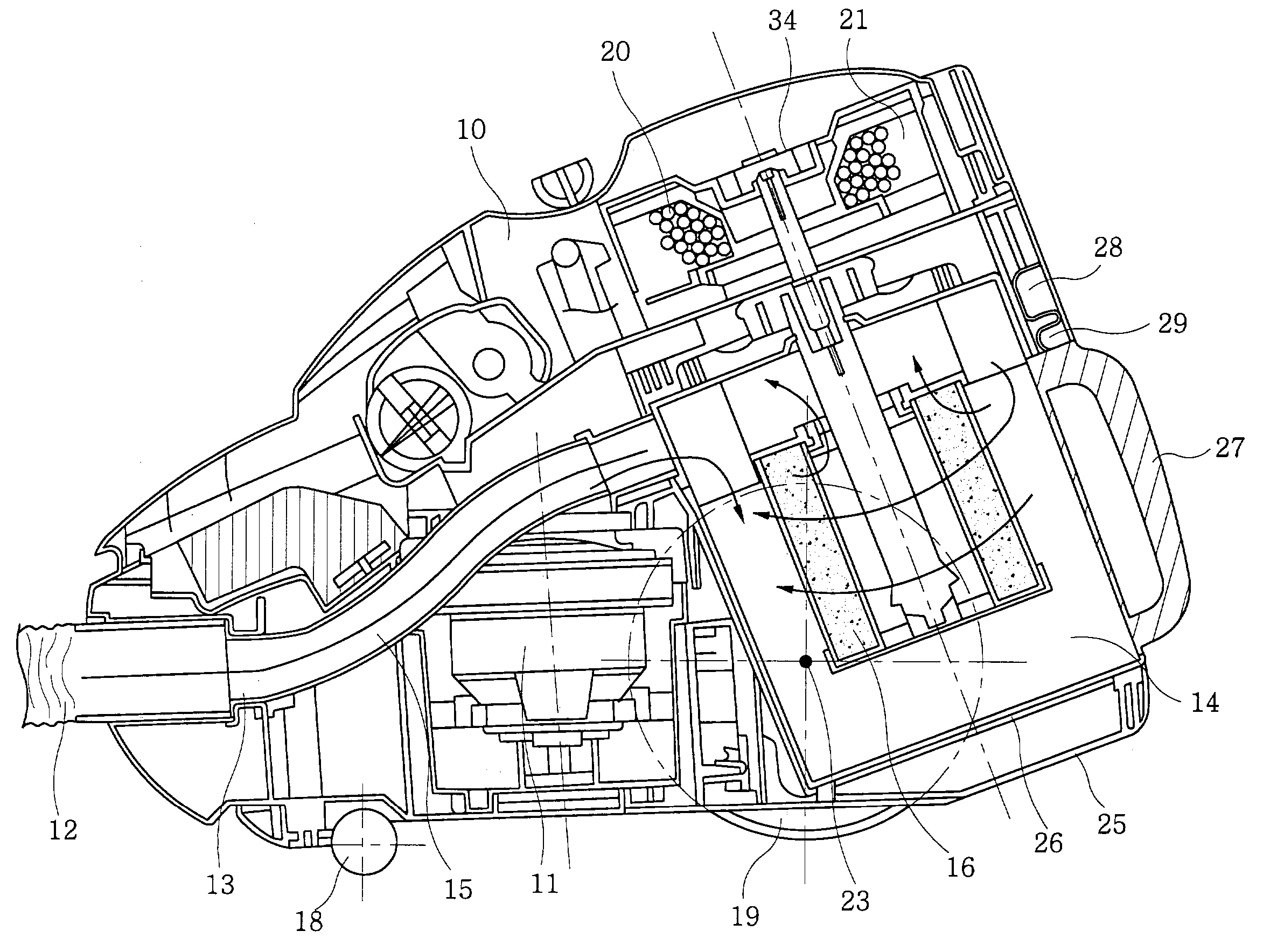
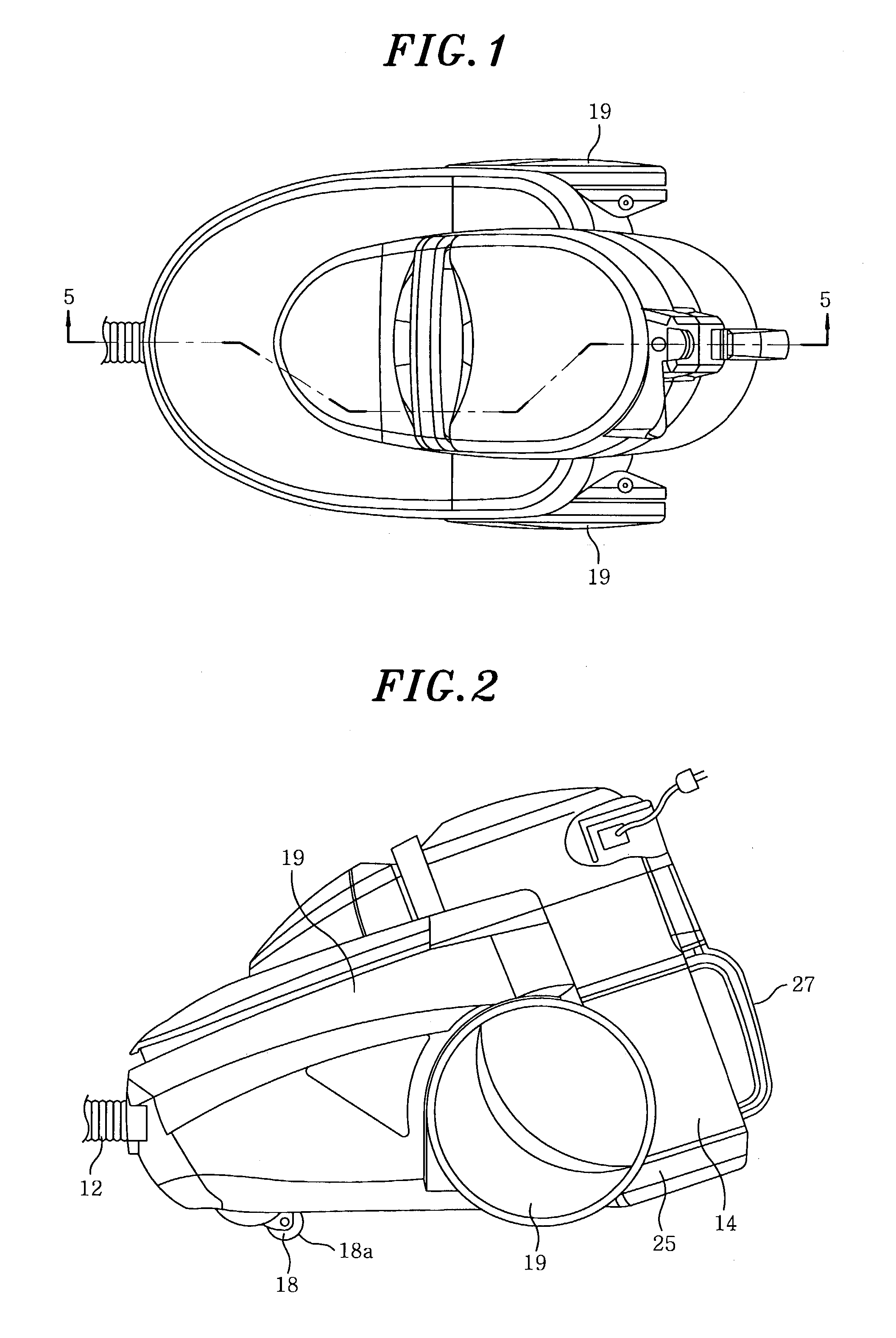
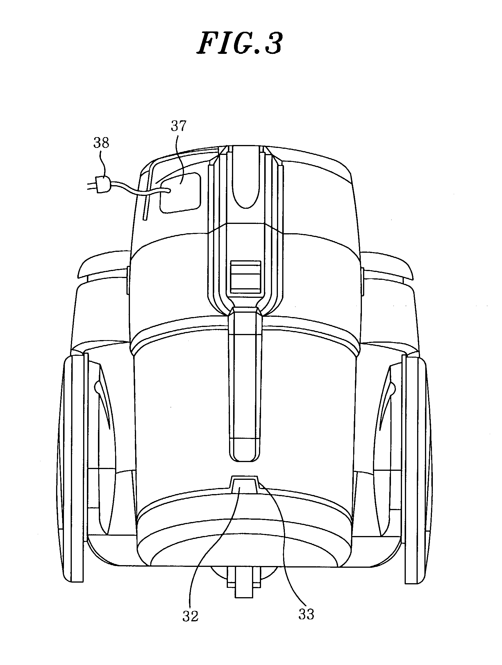
[0025]A first preferred embodiment will now be described with reference to FIGS. 1 to 9, in which there is provided main body 10 incorporating therein electric blower 11 for generating suction air for the intake of dust via hose 12. Hose 12 is detachably secured to suction air inlet 13 located in a front portion of main body 10, while being placed in front of electric blower 11. Detachably placed in a rear portion of main body 10 at the back of electric blower 11 is substantially cylindrical dust chamber 14 making up parts of the rear outer walls of main body 10 for collecting and storing dust therein.

[0026]The dirt-laden air is suctioned and travels from suction air inlet 13 through suction air path 15 and into substantially cylindrical dust chamber 14, at which time the dust is filtered by filter 16, and subsequently, only the air free of dust leaves therefrom. The filtered dust is accumulated in dust chamber 14, whereas the dust-free air travels to electric blower 11 through air ...


PUM


Abstract

A vacuum cleaner has a suction air inlet disposed in front of an electric blower and a dust chamber detachably installed to the rear of the electric blower. The vacuum cleaner further embodies a swivel caster and wheels for facilitating transportability thereof, wherein the swivel caster is provided in front of the electric blower. By not having the dust chamber above the swivel caster, regardless of the amount of dust accumulated in the dust chamber, the load that is distributed on the swivel caster stays substantially unchanged, thereby enhancing durability of the swivel caster. Furthermore, in such configuration loading and unloading of the dust chamber can be carried out without being interfered with a hose due to the placement of the suction air outlet connected with the hose and the dust chamber on opposite ends of the vacuum cleaner.

Description

FIELD OF THE INVENTION[0001]The present invention relates to a vacuum cleaner.BACKGROUND OF THE INVENTION [0002]Conventional vacuum cleaners in general are as disclosed in Japanese Patent Laid-Open Publication No. 1987-15207 as illustrated in FIG. 13.[0003]Referring to FIG. 13, there is provided main body 1 of a vacuum cleaner. Included in a rear region thereof is electric blower 2 for the generation of suction air flow for the intake of dust. Electric blower 2 communicates with a suction nozzle (not shown) for suctioning dirt-laden air. Included in a front region of main body 1 is dust chamber 5 incorporating main filter 3 for filtering fine dust particles and pre-filter 4 for entrapping large dust particles. Dust chamber 5 in air communication with electric blower 2 is detachably installed in main body 1.[0004]Provided in front of dust chamber 5 is suction air inlet 6 communicating therewith for introducing dirt-laden air into main body 1. In order to facilitate transportability o...

Claims


Application Information

Patent Timeline
Patent Type & Authority Patents(United States)
IPC IPC(8): A47L9/10A47L9/26A47L5/36A47L9/16
CPCA47L5/362A47L9/009A47L9/1666A47L9/1683A47L9/26Y10S55/03
Inventor ITO, KOICHINISHIMURA, HIROSHI
Owner PANASONIC CORP
Why Eureka
Try Eureka