Internal combustion engine having valves with variable actuation each provided with a hydraulic tappet at the outside of the associated actuating unit

a technology of variable actuation and internal combustion engine, which is applied in the direction of valve arrangement, machines/engines, non-mechanical valves, etc., can solve the problems of limiting the possibility of substantially instantaneous valve closing phase, and the inability to reduce the diameter of the tappet beyond a certain limit, so as to reduce the diameter of the variable volume chamber

Active Publication Date: 2007-05-01
CENT RICERCHE FIAT SCPA +1
View PDF7 Cites 8 Cited by
  • Summary
  • Abstract
  • Description
  • Claims
  • Application Information

AI Technical Summary

Benefits of technology

[0005]said pressurised fluid chamber being able to be connected by means of a solenoid valve with an exhaust channel, in order to uncouple the variable actuation valve from the respective tappet and cause the rapid closure of the valve by effect of the respective elastic return means,
[0020]Thanks to said characteristic, in the engine according to the invention the dimensioning of the inner diameter of the guide bushing of the actuating piston of the valve becomes completely independent from the outer dimension of the aforesaid auxiliary hydraulic tappet. It is thus possible, in particular, to adopt a guide bushing of the actuating piston with a smaller inner diameter than the outer diameter of said auxiliary hydraulic tappet. Therefore, it is possible considerably to reduce the diameter of said variable volume chamber with respect to known solutions, with consequent possibility of greatly accelerating the valve closing motion.

Problems solved by technology

However, there are limits to the possibility of making the closing phase of the valve substantially instantaneous, which derive in particular from the mass of the moving members, from the load of the elastic means which return the valve to the closed position and from the viscosity of the fluid (the engine lubricating oil) used in the hydraulic system.
However, in known solutions, here too there is a limit to the possibility of reducing said diameter, since the inner diameter of the guide bushing of the actuating piston must be sufficient to house the aforesaid auxiliary hydraulic tappet which is interposed between the actuating piston and the stem of the valve.
If a tappet of any conventional type available on the market is to be used, the diameter of said tappet cannot be reduced beyond a certain limit.

Method used


Image

  • Internal combustion engine having valves with variable actuation each provided with a hydraulic tappet at the outside of the associated actuating unit
  • Internal combustion engine having valves with variable actuation each provided with a hydraulic tappet at the outside of the associated actuating unit
  • Internal combustion engine having valves with variable actuation each provided with a hydraulic tappet at the outside of the associated actuating unit

Examples


Embodiment Construction

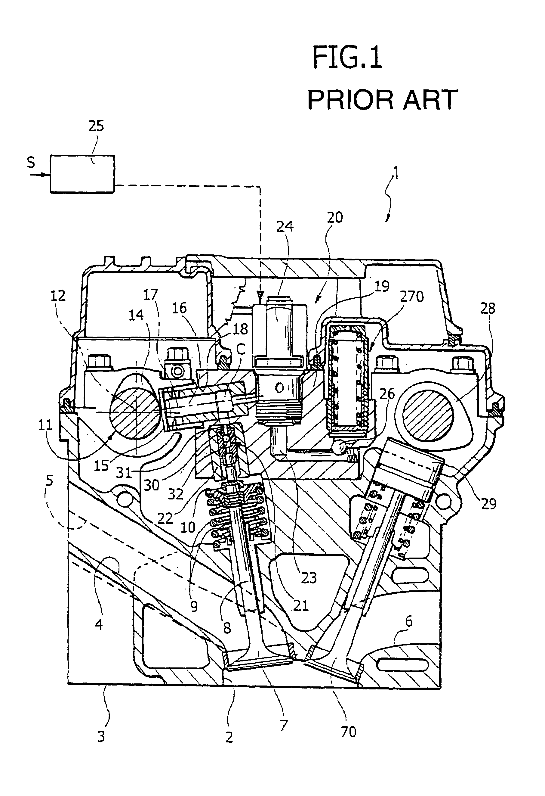
[0027]With reference to FIG. 1, the internal combustion engine described in the prior European patent application EP A 0 803 642 by the same Applicant is a multi-cylinder engine, for instance an engine with four cylinders in line, comprising a cylinder head 1. The head 1 comprises, for each cylinder, a cavity 2 formed in the base surface 3 of the head 1, defining the combustion chamber, into which end two intake conduits 4, 5 and two exhaust conduits 6. The communication of the two intake conduits 4, 5 with the combustion chamber 2 is controlled by two intake valves 7, of the traditional mushroom type, each comprising a stem 8 slidably mounted in the body of the head 1. Each valve 7 is returned towards the closed position by springs 9 interposed between an inner surface of the head 1 and an end cup 10 of the valve. The opening of the intake valves 7 is controlled, in the manner described below, by a camshaft 11 rotatably mounted around an axis 12 within supports of the head 1, and c...


PUM


Abstract

In an internal combustion engine with variable actuation valves, each variable actuation valve is actuated by an actuator assembly including an actuating piston slidably mounted in a guide bushing. Between the actuating piston and the stem of the respective valve is interposed an auxiliary hydraulic tappet comprising a first bushing and a second bushing positioned inside the first bushing in such a way as to define a first chamber between the second bushing and the actuating piston, and a second chamber between the two bushings of the hydraulic tappet. The first chamber is fed a pressurized chamber of the engine lubrication loop. A check valve controls a communication between the two chambers of the tappet, to allow the passage of fluid in the direction of the second chamber. The first bushing of the auxiliary hydraulic tappet is positioned outside the guide bushing of the actuating piston, so that said bushing can be dimensioned with a relatively small diameter, regardless of the outer diameter of the auxiliary hydraulic tappet.

Description

SUMMARY OF THE INVENTION [0001]The present invention relates to internal combustion engines with multiple cylinders, of the type comprising:[0002]at least an intake valve and at least an exhaust valve for each cylinder, each provided with respective elastic return means which bias the valve towards a closed position, to control respective intake and exhaust conduits,[0003]at least a camshaft, to actuate the intake and exhaust valves of the engine cylinders by means of respective tappets,[0004]in which at least each intake valve has variable actuation, being actuated by the respective tappet, against the action of the aforesaid elastic return means, by the interposition of hydraulic means including a pressurised fluid chamber, into which projects a pumping piston connected to the tappet of the intake valve,[0005]said pressurised fluid chamber being able to be connected by means of a solenoid valve with an exhaust channel, in order to uncouple the variable actuation valve from the res...

Claims


Application Information

Patent Timeline
Patent Type & Authority Patents(United States)
IPC IPC(8): F01L1/14F01L9/14F01L1/25
CPCF01L1/25F01L9/025F01L2001/34446F01L9/14
Inventor CANINO, GIANLUCACHIAPPINI, STEFANOVATTANEO, FRANCESCO
Owner CENT RICERCHE FIAT SCPA
Why Eureka
Try Eureka