Apparatus for magnetically separating integrated circuit devices

a technology of integrated circuit devices and magnetic separation, applied in electrical apparatus, solid separation, chemistry apparatus and processes, etc., can solve problems such as inability to respond, and achieve the effect of preventing electrostatic discharge, not damage to ic devices, and not further impairing their operation and performan

Inactive Publication Date: 2007-05-01
MICRON TECH INC
View PDF61 Cites 31 Cited by
  • Summary
  • Abstract
  • Description
  • Claims
  • Application Information

AI Technical Summary

Benefits of technology

[0013]In accordance with another aspect of the invention, an apparatus for sorting IC devices based on ferrous metal content is provided. The apparatus includes a roller having a stainless steel shell and housing a plurality of permanent magnets. A circuitous belt partially circumscribes the roller and is adapted to convey a plurality of IC

Problems solved by technology

Ferrous metal containing IC devices, such as those manufactured with a ferrous alloy lead frame, are attrac

Method used


Image

  • Apparatus for magnetically separating integrated circuit devices
  • Apparatus for magnetically separating integrated circuit devices
  • Apparatus for magnetically separating integrated circuit devices

Examples


Embodiment Construction

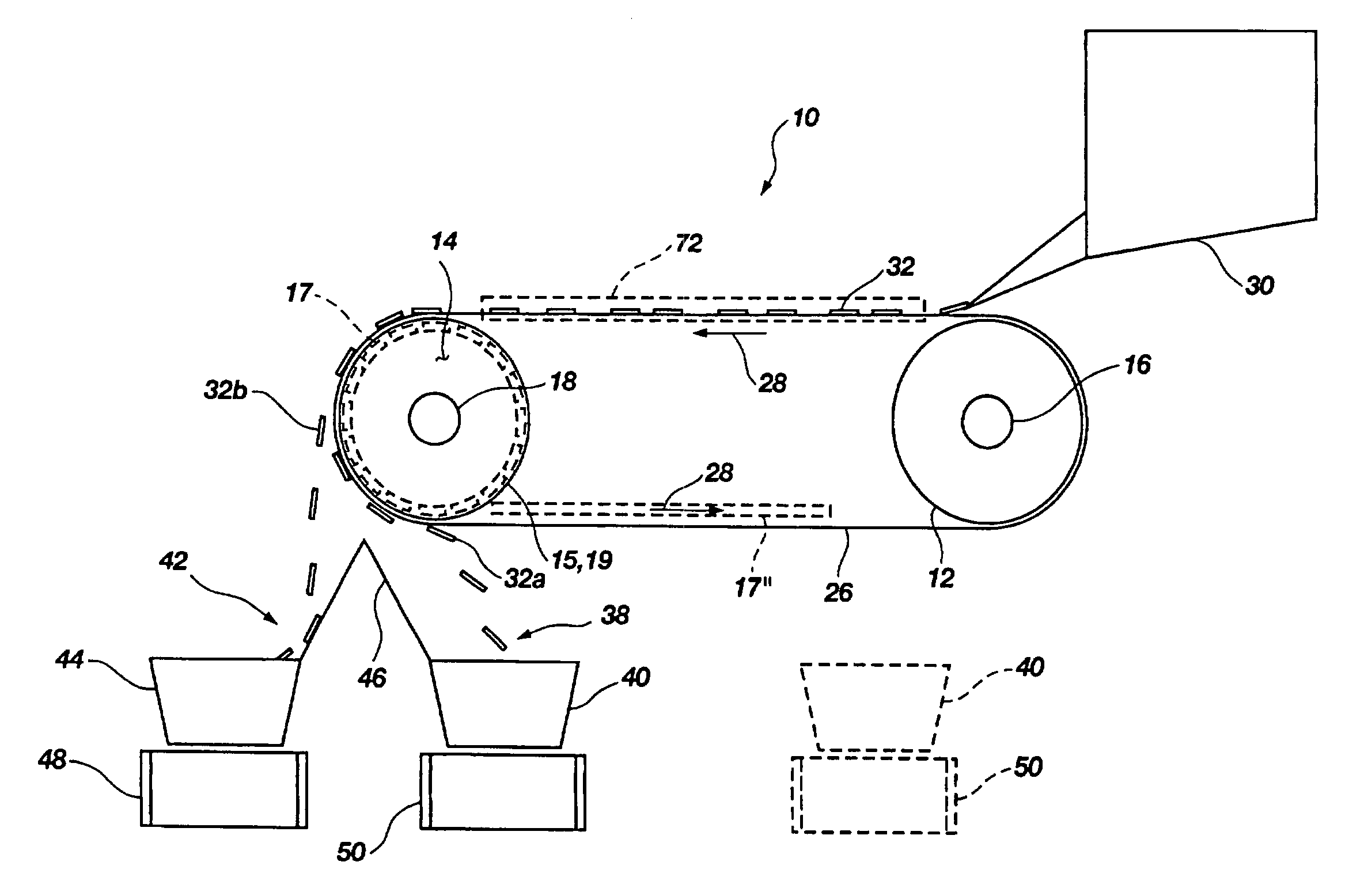
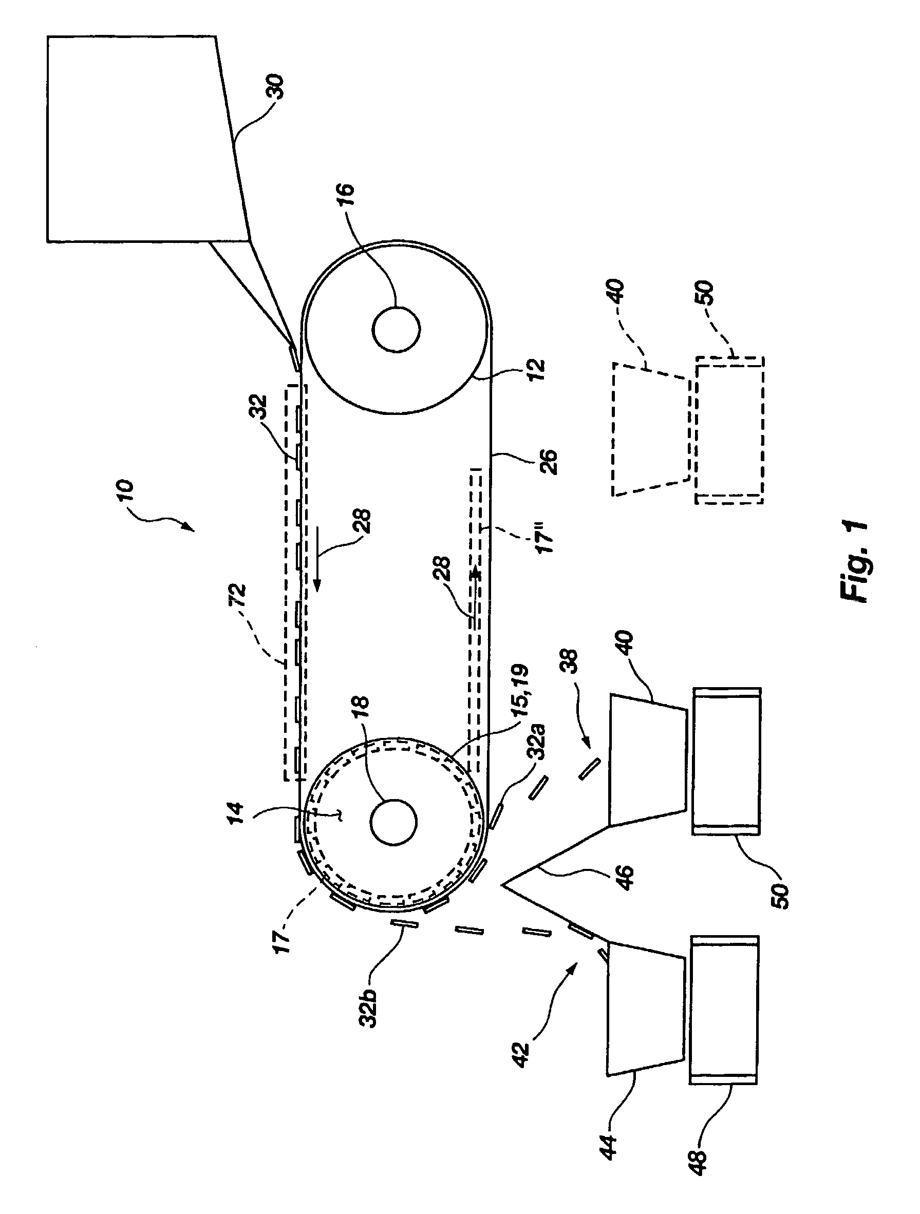
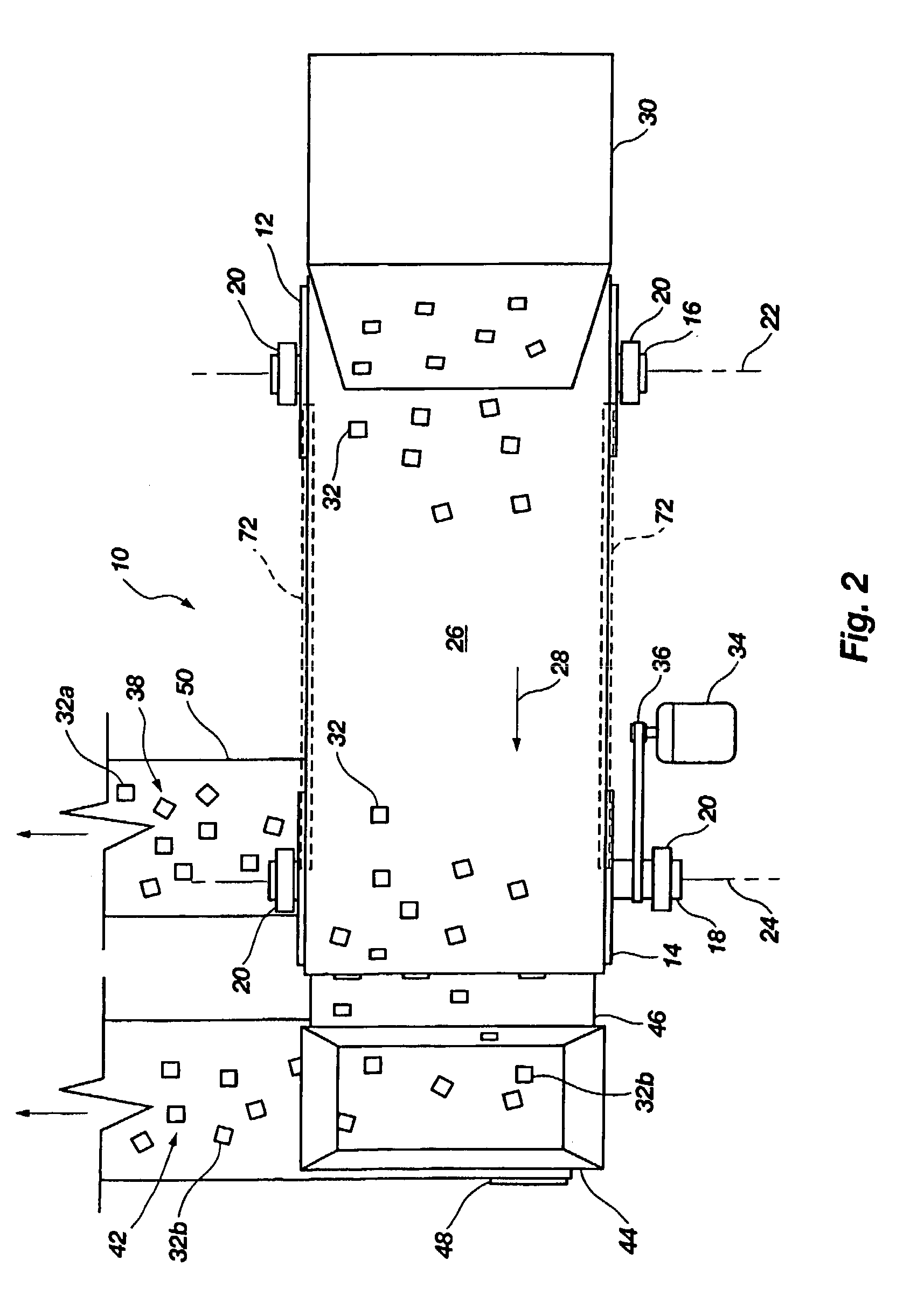
[0023]Referring to FIGS. 1 and 2, a magnetic separating conveyor 10 is shown. The conveyor includes a first roller or end pulley 12 and a second roller or end pulley 14. Each roller 12 and 14 is mounted to a shaft 16 and 18 respectively, the shafts 16 and 18 each being supported by a bearing assembly 20 not in FIG. 1. Each shaft 16 and 18, and thus each roller 12 and 14 is respectively rotatable about an axis 22 and 24. The shafts 16 and 18 may be formed as solid continuous shafts traversing through the width of the rollers, or they may be formed as stub shafts axially aligned at each end of the roller and secured to an external side surface thereof.

[0024]A continuous transport belt 26 is positioned such that it partially circumscribes each roller or end pulley 12 and 14 and extends longitudinally between end pulley 12 and 14. The transport belt 26 travels in a generally circuitous path as indicated by directional arrows 28. Adjacent the first roller 12 is a feeding hopper 30 for di...


PUM


Abstract

A method and apparatus of separating integrated circuit (IC) devices according to magnetic properties of the devices is disclosed. A plurality of IC devices are subjected to a magnetic field. The IC devices containing only nonferrous material are not responsive to the magnetic field and are thus gathered to a first collection site. The IC devices containing ferrous material adhere to a moving surface proximate the magnetic field and are transported to a second collection site. The sorted devices are then transported to separate locations for further processing. The apparatus used for separating the IC devices may include a conveyor having a magnetic drum and an antistatic belt which travels about the magnetic drum. The conveyor allows nonferrous IC devices to fall off the edge of the magnetic drum into the first collection site while transporting the ferrous IC devices to another location for collection.

Description

CROSS-REFERENCE TO RELATED APPLICATION[0001]This application is a divisional of application Ser. No. 09 / 904,365, filed Jul. 12, 2001, now U.S. Pat. No. 6,634,504, issued Oct. 21, 2003.BACKGROUND OF THE INVENTION[0002]1. Field of the Invention[0003]The present invention relates generally to the sorting and classification of integrated circuit (IC) devices. More specifically, the present invention relates to the use of magnetism to separate and sort IC devices based upon the material content of the IC devices.[0004]2. State of the Art[0005]In the art of manufacturing IC devices (also known as semiconductor devices), inspection for quality is routine and often rigorous. Inspection of IC devices may include various techniques known in the art such as subjecting the devices to emission microscopy or X-ray analysis, connecting the IC devices to test circuits cycling the devices at temperature extremes and excessive power inputs and other methods well-known in the art. Such tests are emplo...

Claims


Application Information

Patent Timeline
IPC IPC(8): B03C1/00B03C1/16H05K13/02
CPCB03C1/00B03C1/16H05K13/028B03C1/0332B03C1/034B03C1/18B03C1/22B03C2201/20
Inventor ROBINSON, KEITH E.POULSON, WILLIAM L.VULCAN, IONEL
Owner MICRON TECH INC
Why Eureka
Try Eureka