
Power consumption protocol

a power consumption protocol and power consumption technology, applied in vehicle tyre testing, instruments, roads, etc., can solve the problems of affecting the number and frequency of data transmissions that can be relayed for processing, and affecting the processing efficiency of power consumption protocols

Inactive Publication Date: 2007-05-01
PIEZOTAG LTD
View PDF3 Cites 13 Cited by
  • Summary
  • Abstract
  • Description
  • Claims
  • Application Information

AI Technical Summary

Benefits of technology

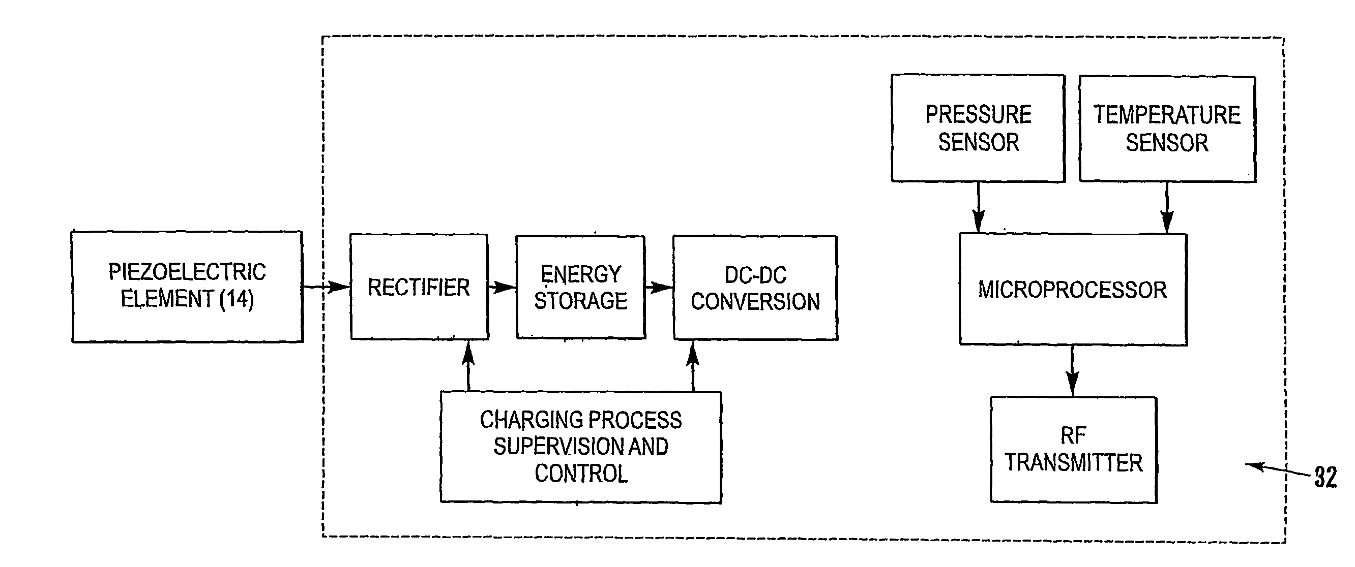
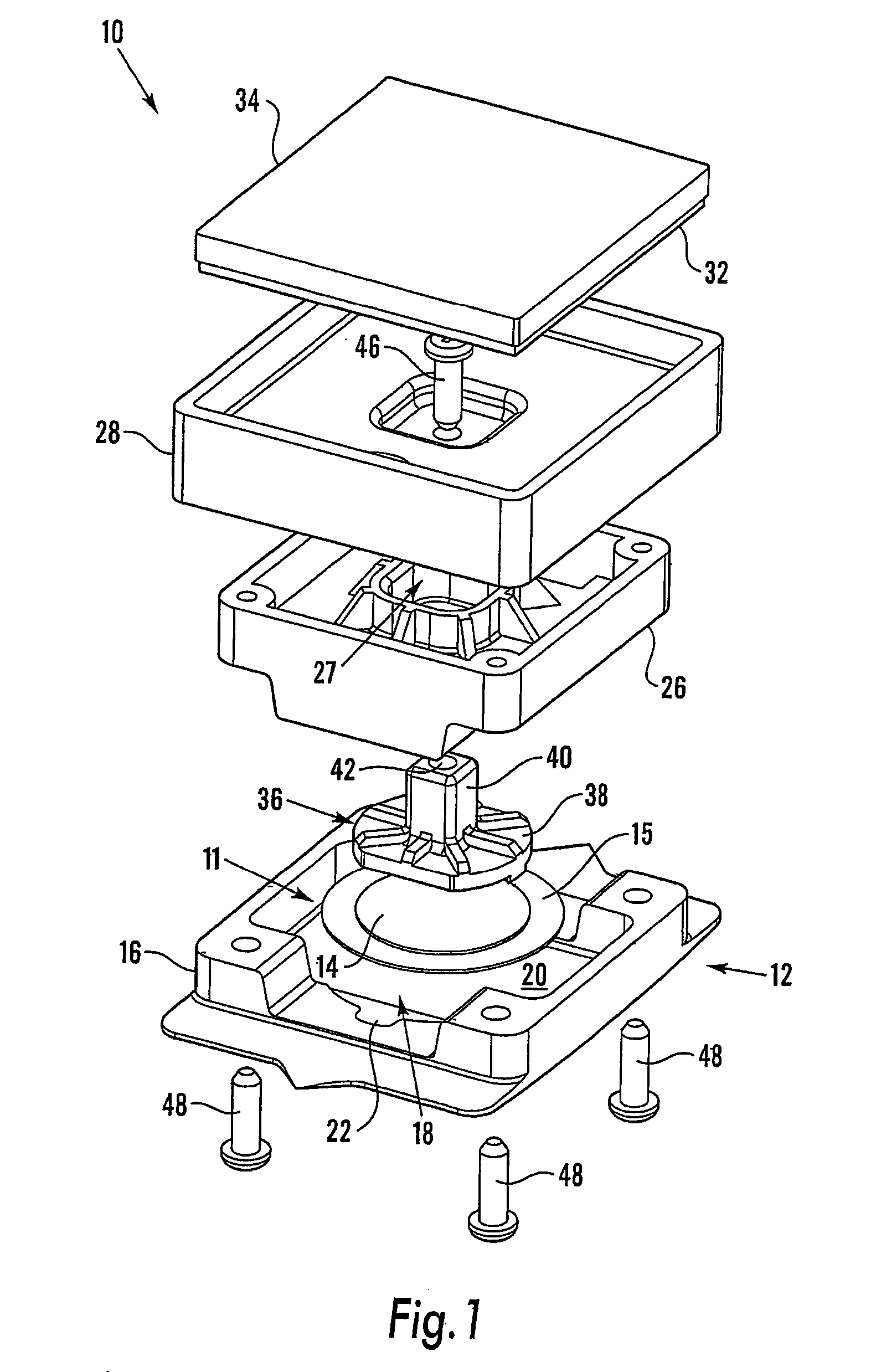
[0014]The invention is of primary advantage when used with a telemetry unit in which the power source is a piezoelectric element, for selectively controlling the consumption of the small amounts of charge generated by the piezoelectric element, in particular for a tyre monitoring apparatus.

Problems solved by technology

Such arrangements have several undesirable limitations, for example limited battery life and size or weight which can be accommodated within a tyre.
This can have a further undesirable knock on effect, in that if there is a limited power source available, for example as a result of weight implications, the number and frequency of data transmissions that can be relayed for processing is compromised.

Method used


Image

  • Power consumption protocol
  • Power consumption protocol
  • Power consumption protocol

Examples


example 1

Stage 1

[0052]The micro processor is in ‘sleep’ mode, in which all internal processing is suspended, apart from a monitor circuit, for monitoring the ‘wake up’ requirements of the micro processor. In this embodiment, the monitor circuit monitors an externally referenced clock in the form of a crystal oscillator, located outside the micro processor in the unit. Hence, in sleep mode, the majority of the micro processor circuitry is disabled and the power consumption of the tyre monitoring apparatus is at a minimum level, for example approximately 24 micro ampere of supply current.

Stage 2

[0053]After a predetermined time, in this embodiment 60 seconds, the monitor circuit ‘wakes up’ the micro processor. Upon ‘wake up’, the micro processor switches from the external clock to an internal clock, in the form of an internal resistor capacitor oscillator. This switch is implemented to facilitate a higher speed operation of the analogue to digital conversions and subsequent calculations which a...

example 2

Stage 1

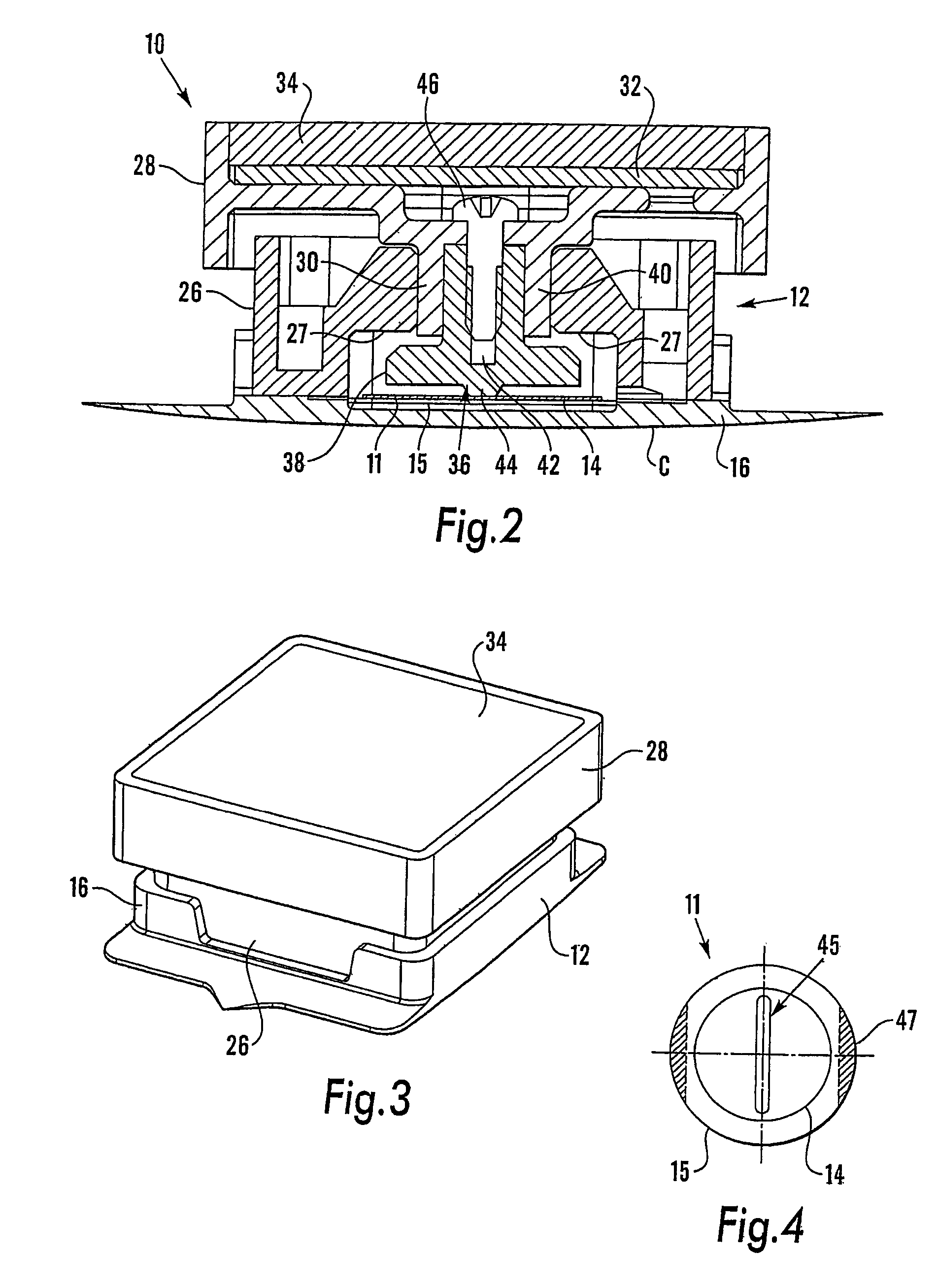
[0067]As the wheel rotates, storable power outputs are produced by the power generator, one per revolution, as described above. In this example, this characteristic of the power generator is used to monitor the speed of the vehicle and / or the state of charge of the capacitors. A small portion of each storable power output is signal conditioned to take in to consideration false triggers of power which may be experienced by the piezoelectric disc 14 during rotation of the wheel, for example accelerations / deflections which are caused by vibrations due to imperfections in the road surface. The conditioned signal is then supplied to an interrupt circuit in the micro processor, which momentarily wakes the micro processor from its sleep mode and increments a counter in the micro processor. The micro processor then returns instantly to the sleep mode.

Stage 2

[0068]Both the average charge generated per revolution of the wheel and the value of stored charge sufficient to measure and tra...


PUM


Abstract

Low power consumption protocol A telemetry unit (100) is provided for mounting inside a pneumatic tire, which includes a piezoelectric element (114) supported in a housing (112), with an actuator (136) arranged for contact with the element (114), to deflect the element (114) in response to external forces acting on the actuator (136) during rotation of the tire. For every rotation of the tire, cyclic pulses of electrical charge are generated by the deflection of the element (114). The charge is stored and utilised under a power consumption protocol including the steps of: initiating power to a data measurement circuit for measuring data from the environment local to the unit (100); disabling power to the data measurement circuit; initiating power to a data transmission circuit; transmitting data from the measurement circuit; and disabling power to the transmission circuit. The power consumption protocol therefore minimises consumption of the generated power, during measurement and transmission of data by the unit (100).

Description

BACKGROUND OF THE INVENTION[0001]The present invention relates to a power consumption protocol or method for selectively controlling the power consumption of a telemetry unit having a power source. The invention is of particular advantage in controlling the consumption of power from a piezoelectric power generator, for supplying power to a remote telemetry apparatus for transmitting data from a rotatable body, for example from within a pneumatic tyre.[0002]It is known to provide a tyre monitoring apparatus for measuring the pressure within vehicle tyres. The tyre monitoring apparatus may also measure other parameters within a tyre environment, such as the local temperature of a tyre. The measured data is transmitted, for example via a radio wave link, to the cabin of the vehicle where it is electronically processed before being displayed to the vehicle driver. This enables the recipient of the transmitted data to monitor changes in the condition of the tyre, for example to reduce da...

Claims


Application Information

Patent Timeline
Patent Type & Authority Patents(United States)
IPC IPC(8): B60C23/00B60C23/02B60C23/04
CPCB60C23/0408B60C23/0411B60C23/0493
Inventor HASWELL, GEOFFREYFAWCETT, SIMON WILLIAMHOLDSWORTH, PAUL REECEBOWLES, STEPHEN JOHNGARCIA-HERNANDEZ, MIGUEL JESUSTURO-PEROY, ANTONIOSMART, DAVID MATTHEWCHAVEZ-DOMINGUEZ, JUAN ANTONIOSALAZAR-SOLER, JORDI
Owner PIEZOTAG LTD
Learn More