Low-profile embedded antenna architectures for wireless devices

a wireless device and embedded antenna technology, applied in the direction of resonant antennas, portable computers, instruments, etc., can solve the problems of adverse device appearance, high manufacturing cost and susceptibility to antenna damage, adverse antenna performance, etc., to achieve good antenna characteristics, maintain radiation efficiency and impedance matching, and high radiation efficiency

Active Publication Date: 2007-05-01
LENOVO PC INT
View PDF7 Cites 30 Cited by
  • Summary
  • Abstract
  • Description
  • Claims
  • Application Information

AI Technical Summary

Benefits of technology

[0007]The slotted region is patterned to minimize or eliminate the out-of-phase currents that are induced by the radiating element on the ground element adjacent to the radiating element, which enables the height of the planar radiator above the planar ground element to be significantly reduced for a given operating bandwidth while maintaining the radiation efficiency and impedance matching within the given operating bandwidth. In other words, currents induced on the ground plane close to the radiator are controlled for high radiation efficiency by slotting or notching the ground plane.
[0008]In accordance with exemplary embodiments of the invention, height-reduction methods and impedance matching techniques are used for designing low-profile INF (inverted-F) type and UWB (ultra-wide band) type antennas. For example, a low-profile inverted-F (INF) antenna with a slotted ground plane according to an exemplary embodiment of the invention for operation in the 2.45 GHz ISM band is provided, which enables the antenna height to be reduced to ½ of the height of a low-profile INF antenna with a non-slotted ground plane, while maintaining good antenna characteristics.
[0009]In addition, a low-profile UWB planar monopole antenna with a slotted ground plane according to an exemplary embodiment of the invention for operation in the wireless 3.1 GHz–10.6 GHz UWB band is provided, which enables the antenna height to be about 6 mm or less and thickness of 0.5 mm, which is significantly smaller than conventional UWB designs with non-slotted ground planes, while maintaining good antenna characteristics. In other exemplary embodiments of the invention, low-profile UWB antennas are designed with double feeding schemes to improve impedance matching over a wide operating bandwidth.

Problems solved by technology

However, there are disadvantages associated with external antenna designs including, for example, high manufacturing costs and susceptibility of antenna damage, as well as the adverse appearance of the device due to the external antenna.
However, when antennas are embedded within the housing of computing devices with limited space and lossy environments, antenna performance can be adversely affected.
However, as computing devices are made smaller with increasingly limited space, embedded antennas must be designed with more compact structures and profiles, which is problematic.

Method used


Image

  • Low-profile embedded antenna architectures for wireless devices
  • Low-profile embedded antenna architectures for wireless devices
  • Low-profile embedded antenna architectures for wireless devices

Examples


Embodiment Construction

[0026]In general, exemplary embodiments of the invention include compact embedded antenna designs for use with computing devices to enable wireless connectivity and communication. For illustrative purposes, exemplary embodiments of the invention will be described in detail hereafter with regard to low-profile embedded antenna designs and methods for embedding low-profile antennas within display units of portable laptop computers (e.g., IBM ThinkPad computer), but nothing herein shall be construed as limiting the scope of the invention.

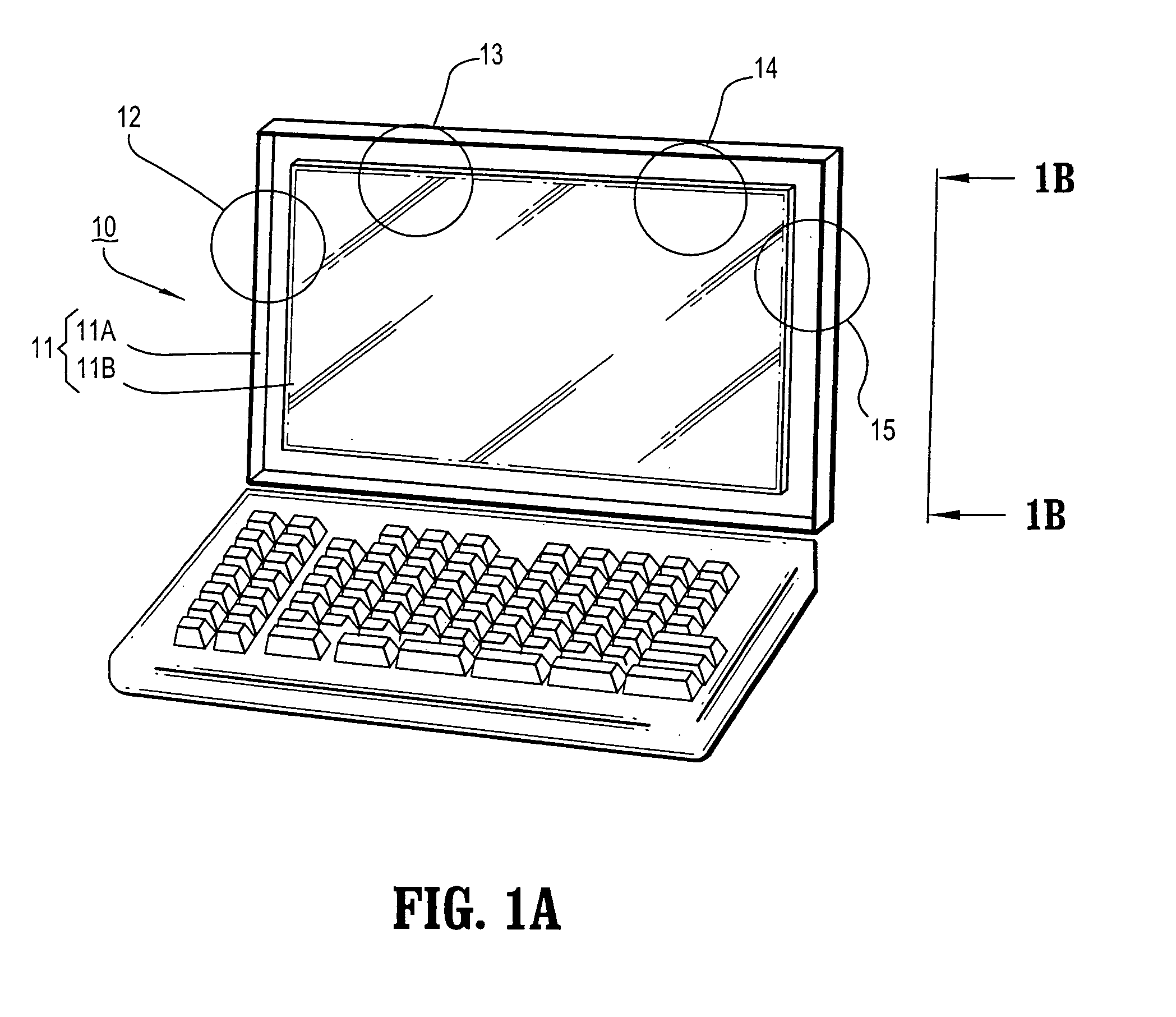
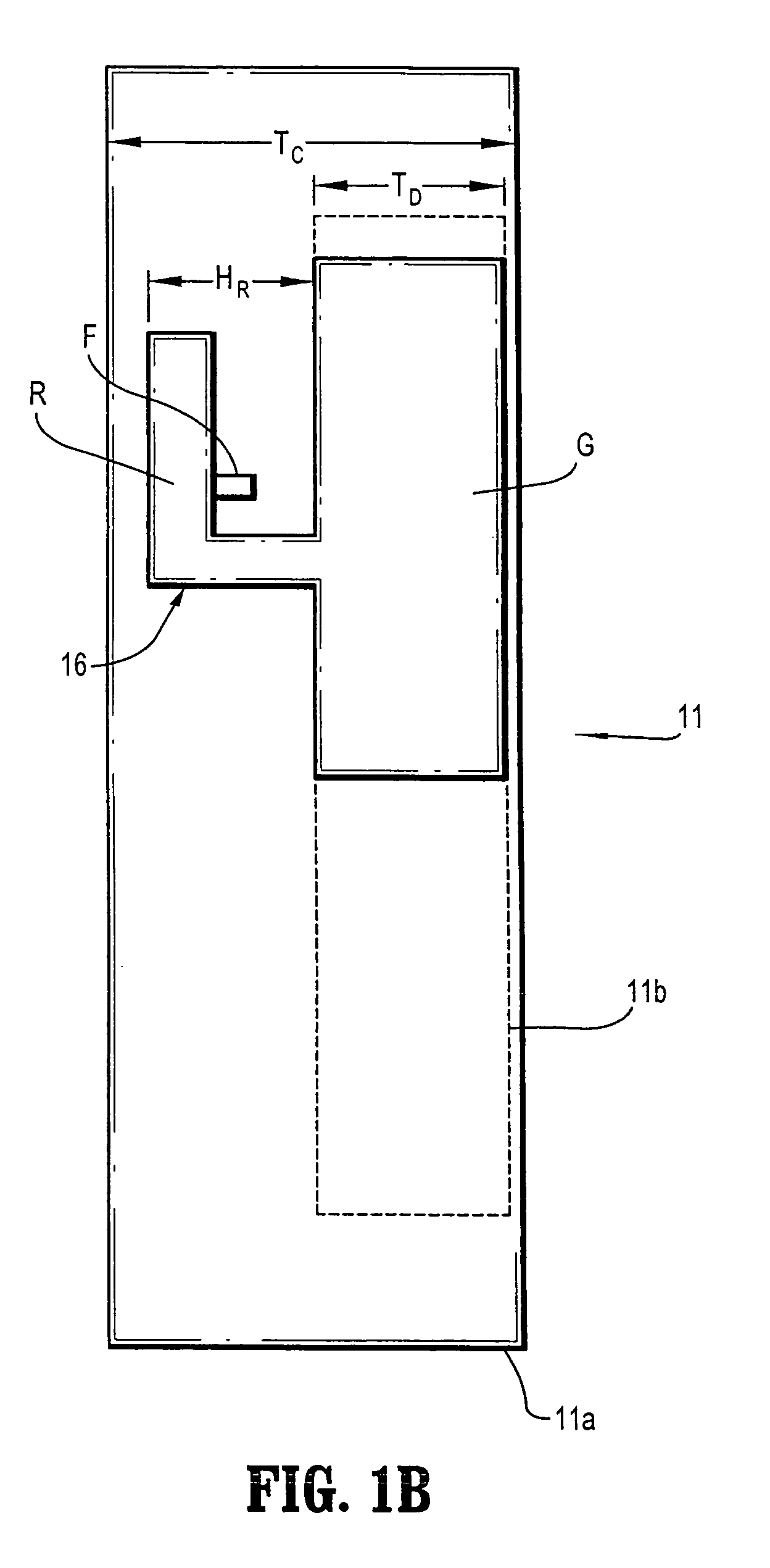
[0027]FIGS. 1A and 1B schematically illustrate methods for embedding antennas within the display unit of a portable laptop computer, according to exemplary embodiments of the invention. In particular, FIG. 1A is a schematic perspective view of a laptop computer (10) having a display unit (11). The display unit (11) comprises a display cover (11a), a display panel (11b), and metal hinge bars (not shown) that securely supports the display panel (11b) to ...


PUM


Abstract

Low-profile, compact embedded antenna designs are provided for use with computing devices, such as laptop computers, which enable ease of integration within computing devices with limited space, while providing suitable antenna characteristics (e.g., impedance matching and radiation efficiency) over a desired bandwidth of operation. Compact antenna designs with reduced antenna size (e.g., antenna height) and increased operational bandwidth (e.g., broadband impedance matching) are achieved using slotted ground plane designs and / or doubling antenna feeding schemes.

Description

TECHNICAL FIELD OF THE INVENTION[0001]The present invention relates generally to embedded antenna designs for use with computing devices, such as laptop computers, to enable wireless connectivity and communication. More specifically, the invention relates to low-profile, compact embedded antenna designs that enable ease of integration within wireless devices with limited space, while providing suitable antenna characteristics and performance such as impedance matching and radiation efficiency over a wide bandwidth of operation.BACKGROUND[0002]Wireless connectivity and communication between devices in wireless networks / systems such as WPAN (wireless personal area network), WLAN (wireless local area network), WWAN (wireless wide area network), and cellular networks, for example, can be achieved by equipping wireless devices with antennas. For example, a WLAN may operate under the known “Bluetooth” standard to provide wireless network connectivity between devices such as a portable lap...

Claims


Application Information

Patent Timeline
Patent Type & Authority Patents(United States)
IPC IPC(8): H01Q1/24
CPCG06F1/1616G06F1/1698H01Q1/22H01Q1/2266H01Q1/48H01Q9/42
Inventor CHEN, ZHI NINGGAUCHER, BRIAN PAULHILDNER, THOMAS RICHARDLIU, DUIXIAN
Owner LENOVO PC INT
Why Eureka
Try Eureka