
Method and apparatus for maximizing a data rate of a wireless data communication system

Active Publication Date: 2007-05-01
GOOGLE TECH HLDG LLC
View PDF12 Cites 18 Cited by
  • Summary
  • Abstract
  • Description
  • Claims
  • Application Information

AI Technical Summary

Benefits of technology

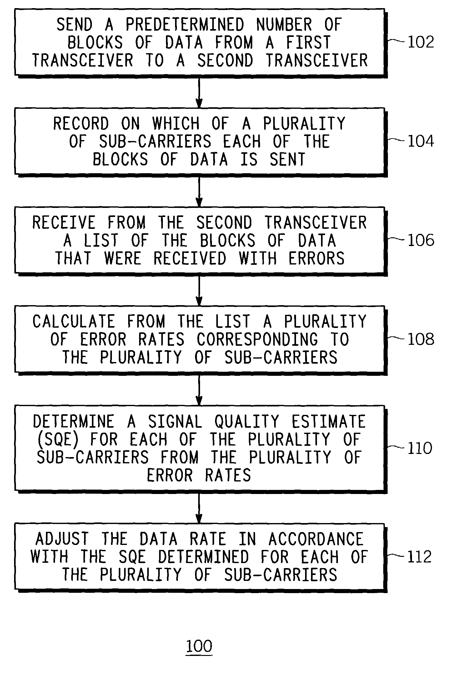
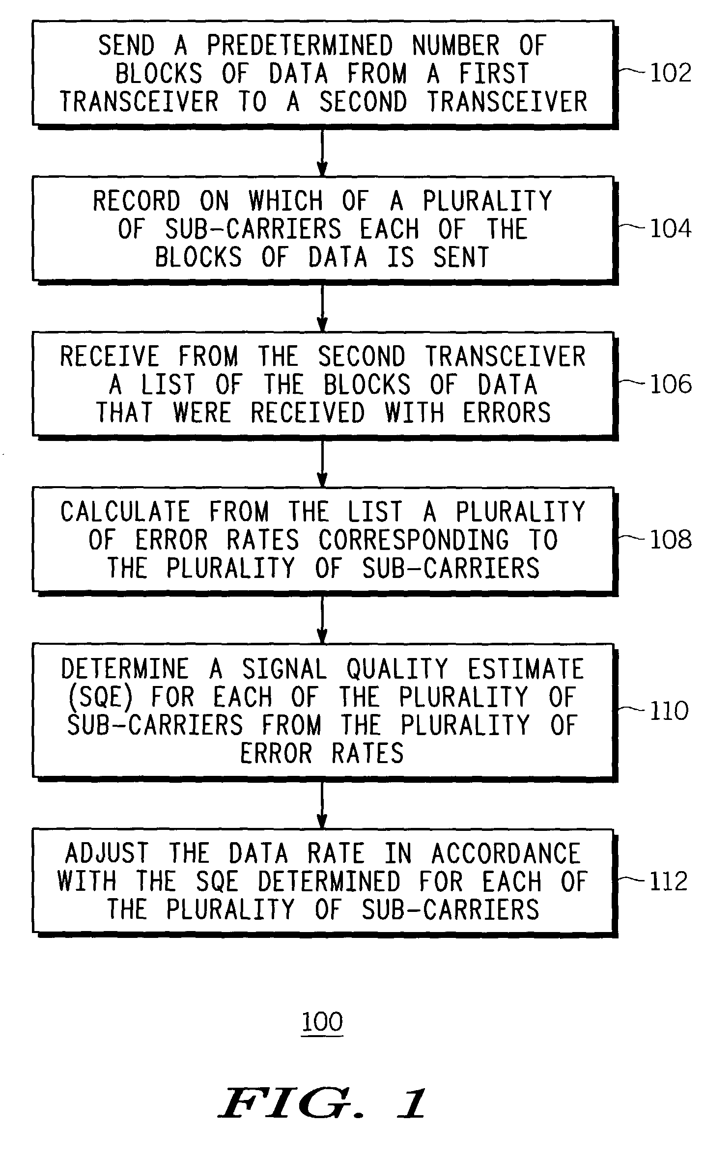
[0006]FIG. 1 is a flow diagram of a method for maximizing a data rate of a wireless data communication system.
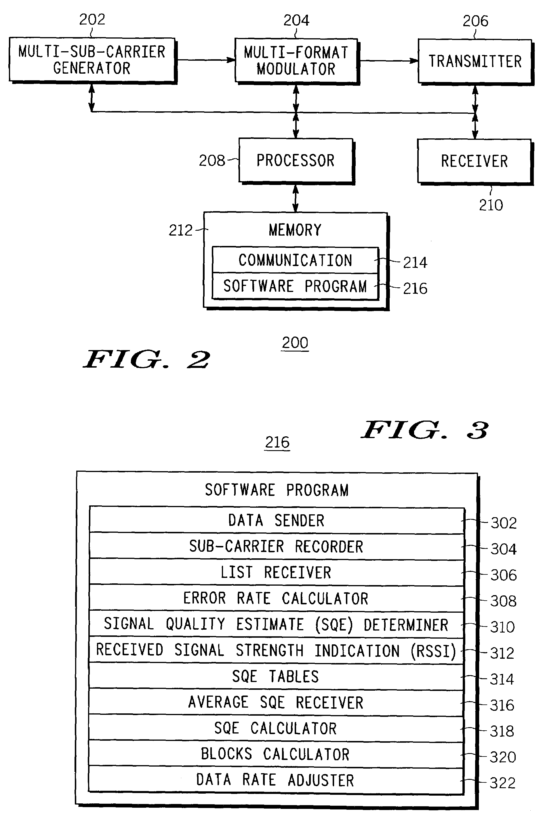
[0007]FIG. 2 is an electrical block diagram of an exemplary transceiver for maximizing the data rate.

Problems solved by technology

The prior-art technique presents two problems.
The first problem is that measuring the SQE on all sub-carriers simultaneously can consume more processing power than may be readily available in the second transceiver.
The second problem is that feeding back the SQE results from the second transceiver to the first transceiver requires bandwidth on the reverse link.
Bandwidth that is allocated to SQE data represents an undesirable overhead.

Method used


Image

  • Method and apparatus for maximizing a data rate of a wireless data communication system
  • Method and apparatus for maximizing a data rate of a wireless data communication system
  • Method and apparatus for maximizing a data rate of a wireless data communication system

Examples


first embodiment

[0026]The first embodiment advantageously requires no explicit feedback from the second transceiver to the first transceiver about the SQE. The first transceiver estimates the SQE based on the layer-two data transmission reported errors. The first transceiver transmits a Medium Access Layer Normal Transmission Unit (MAC NTU) consisting of several blocks of transmitted data, using an initial modulation format. The first transceiver records on which sub-carrier each block is transmitted.

[0027]The second transceiver receives the data and sends back to the first transceiver a list of blocks that are received with errors in the form of a Selective Automatic Retransmission reQuest (S-ARQ). (In the prior-art system, the transmitting entity only uses the S-ARQ information to retransmit the blocks received with errors.) In the first embodiment, the first transceiver uses the S-ARQ feedback and the first transceiver's records concerning on which sub-carrier each block was transmitted, to deri...

second embodiment

[0033]The second embodiment uses an average full signal SQE measurement reported back to the first transceiver to estimate the individual sub-carrier SQEs. This method advantageously reduces the bandwidth required for reporting SQE measurements back to the first transceiver, compared to the prior-art method. Instead of reporting an SQE measurement for each sub-carrier, the second transceiver reports only the average SQE, and the first transceiver uses the block error rates that are readily available to estimate the SQE on each sub-carrier. This may be done in several ways. A preferred method is as follows:

[0034]Let SQEavg be the full bandwidth SQE. SQEi, which represents the SQE for sub-carrier i is derived as follows:

[0035]The average SQE selects a point in a pre-stored SQE-to-block-error-rate curve saved in the first transceiver. The sub-carriers are ordered in ascending block error rate:

[0036]C1-C2-C3-C4, where the corresponding error rates are E1, E2, E3, E4.

[0037]Starting from ...


PUM


Abstract

A first transceiver (200) sends (102) a predetermined number of blocks of data to a second transceiver, and records (104) on which of a plurality of sub-carriers each of the blocks of data is sent. The first transceiver receives (106) from the second transceiver a list of the blocks of data that were received with errors, and calculates (108) from the list a plurality of error rates corresponding to the plurality of sub-carriers. The first transceiver then determines (110) the SQE for each of the plurality of sub-carriers from the plurality of error rates, and adjusts (112) the data rate in accordance with the SQE determined for each of the plurality of sub-carriers. These processes can be implemented as a method that is facilitated by a software program.

Description

FIELD OF THE INVENTION[0001]This invention relates in general to wireless data communication systems, and more specifically to a method and apparatus for maximizing a data rate of a wireless data communication system.BACKGROUND OF THE INVENTION[0002]The desire for increased transmission data rates in today's wireless data communication systems has led some systems to a technique of sending data over multiple parallel sub-carriers simultaneously, each sub-carrier having its own dedicated carrier frequency. In such prior-art multi-sub-carrier systems, it has been the practice for a first transceiver to send an amount of data to a second transceiver, after which the second transceiver makes multiple signal quality estimates (SQEs) corresponding to the signal received on each of the multiple sub-carriers. The second transceiver then reports the multiple SQEs to the first transceiver, which then accordingly adjusts the data rate of a subsequent transmission to the maximum consistent with...

Claims


Application Information

Patent Timeline
IPC IPC(8): H04J15/00H04B1/00H04B1/02H04J99/00H04L1/00H04L1/16H04L1/18H04L1/20H04L27/26
CPCH04L1/0003H04L1/0015H04L1/0026H04L1/0034H04L1/20H04L1/16H04L1/18H04L27/2608
Inventor KHAWAND, JEAN
Owner GOOGLE TECH HLDG LLC
Learn More