Vibration actuator device of portable terminal
a portable terminal and actuator technology, applied in the direction of electrical transducers, shock absorbers, mechanical instruments, etc., can solve the problems of difficult to set the resonance point, air vibration, sharp drop in the amount of bodily-sensible vibration, etc., and achieve the effect of restricting the amount of air
- Summary
- Abstract
- Description
- Claims
- Application Information
AI Technical Summary
Benefits of technology
Problems solved by technology
Method used
Image

Examples
first embodiment
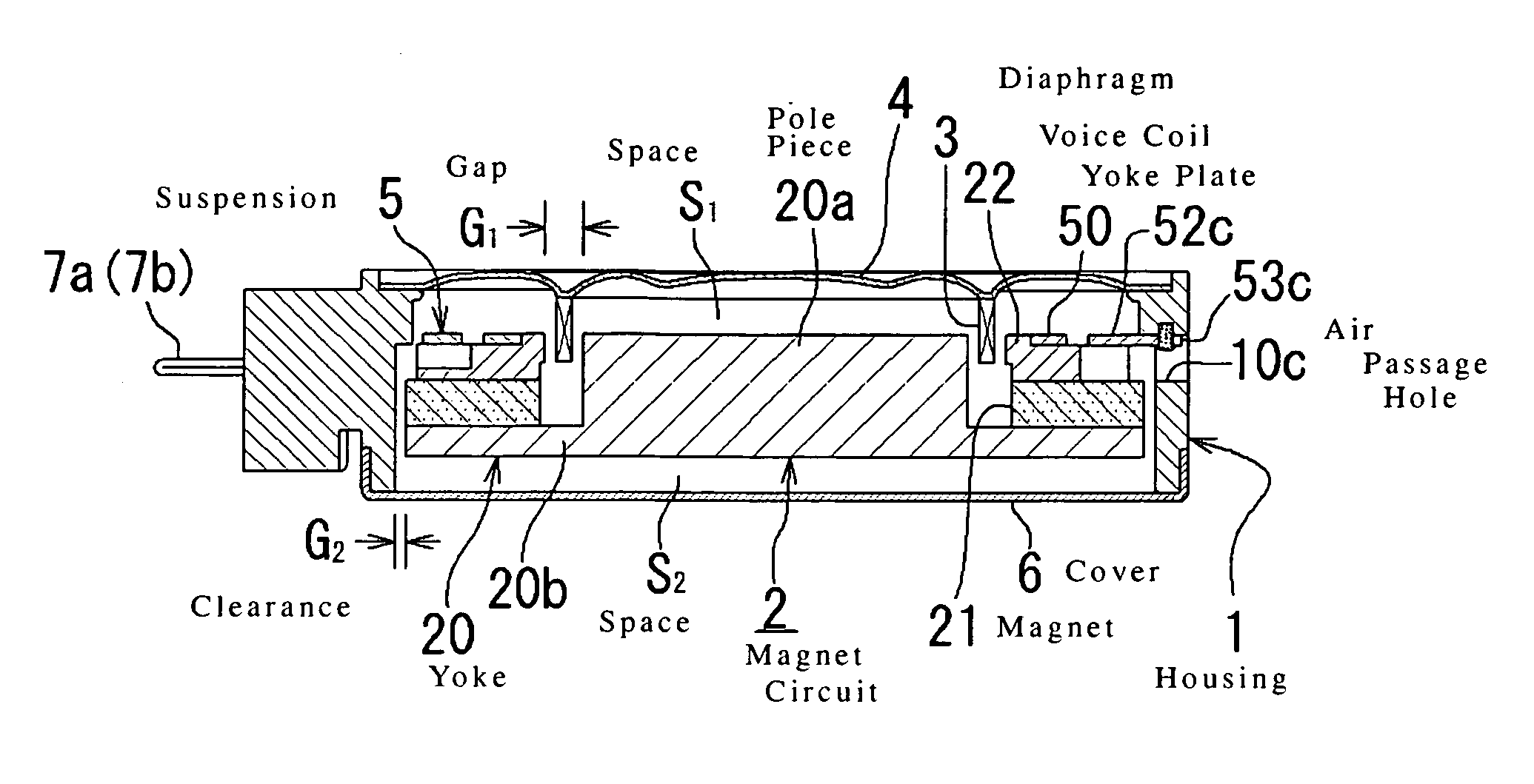
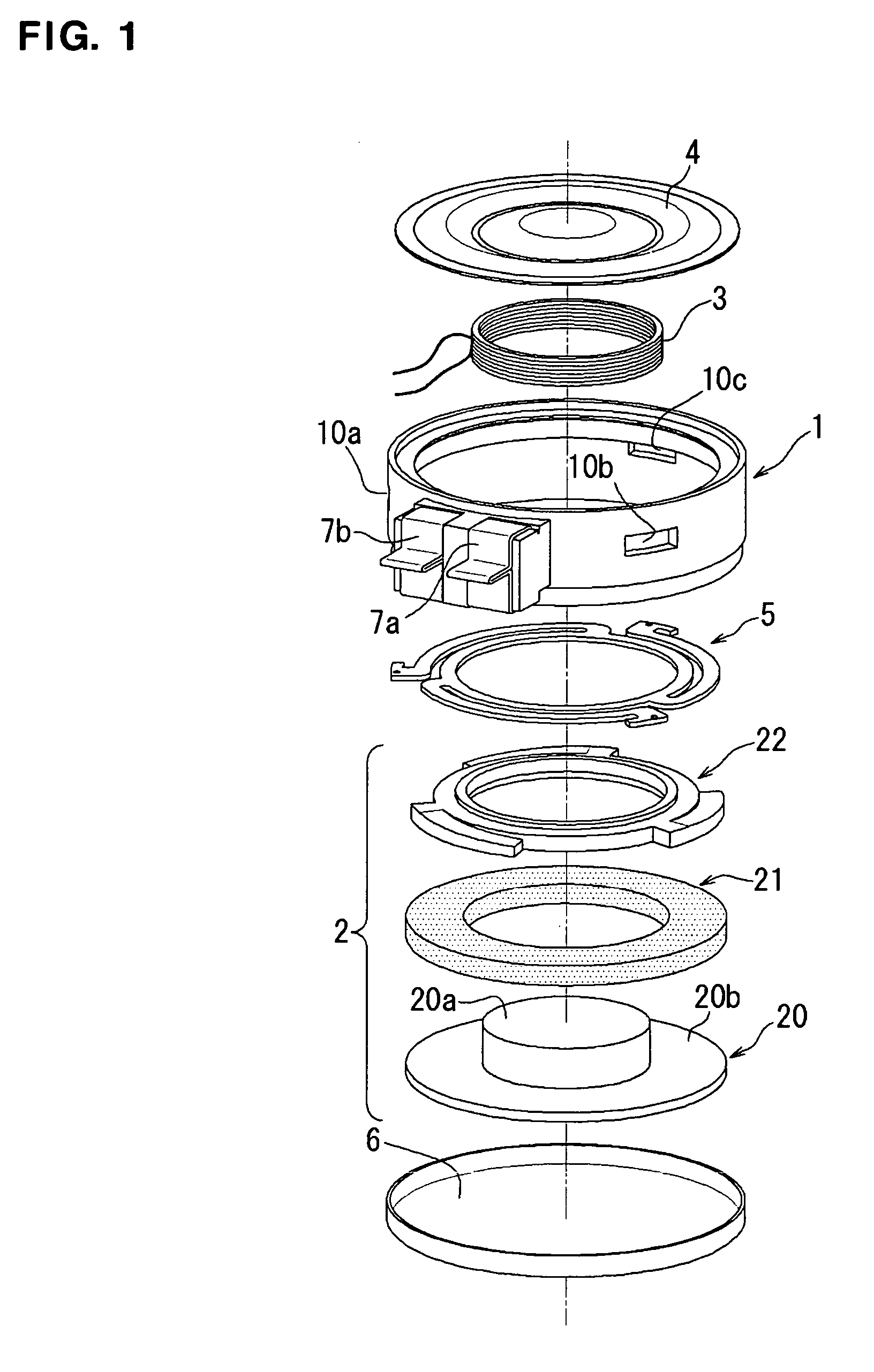
[0073]In the first embodiment, as shown in FIGS. 1 and 6, a number of air passage holes 10a through 10c have been opened in the side of the housing 1. Further the outer surface of the round plate 20b of the yoke 20 has been made to closely approach the inner surface of the housing 1, and so a clearance G2 is formed between the outer surface of the yoke and the inner surface of the housing. This limits the amount of reciprocal movement of the interior air in the space S1 formed by the diaphragm 4 and the magnetic circuit 2 and the interior air in the space S2 formed by the magnetic circuit 2 and the cover 6.
[0074]In this embodiment there are, in the side of the housing 1, three air passage holes (see 10a through 10c in FIG. 1) to match the number of spring arms 52a through 52c of the suspension 5; these air passage holes are also used for attachment of the attachment blades (see 53a through 53c in FIG. 1) on the spring arms (see 10c and 53c of FIG. 6). By this means, the suspension 5...
second embodiment
[0085]In the second embodiment, in order to meet these demands, the size of the yoke 20 is changed in the facial direction (in the direction of the diameter of the round plate 20b). Specifically, the yoke is made variously within the range in which the interior air functions as a damper; that is, where the clearance measurement relative to the inner radius of the housing is more than 0% and not more than 2.5%, or more than 0 mm and not more than 0.2 mm, preferably at least 0.05 mm and not more than 0.15 mm. By adjusting and limiting the movement of interior air between spaces S1 and S2 in this way, it is possible to adjust the damping action that the air puts on the up and down vibration of the magnetic circuit.
[0086]By enlarging the size of the clearance G2, it becomes possible to increase the acceleration as modeled in FIG. 10. By reducing the size of the clearance G2, on the other hand, it is possible to gently reduce the acceleration and expand the frequency range.
[0087]Now, in ...
third embodiment
[0094]The third embodiment is constituted to set and change the bodily-sensible vibration characteristics by placing through holes 12a through 12c in the yoke 20, as shown in FIG. 13, in addition to the air passage holes 10a through 10c and the clearance G2 described above. The through holes 12a through 12c are bored through the yoke 20 in order to regulate and limit the amount of movement of interior air between spaces S1 and S2.
[0095]The positions for piercing the through holes can be selected from both the pole piece 20a and the round plate 20b, as shown in the drawing, or either the pole piece 20a or the round plate 20b. The number of holes should be one or two, from the need to maintain the weight balance of the magnetic circuit, or that can be changed to three or six spaced at regular intervals around the periphery.
[0096]Assuming a fixed value for the power of the electrical signal impressed on the voice coil, it is possible to bring about different vibration characteristics d...
PUM
 Abstract
Description
Claims
Application Information
 - R&D
- Intellectual Property
- Life Sciences
- Materials
- Tech Scout
- Unparalleled Data Quality
- Higher Quality Content
- 60% Fewer Hallucinations
Browse by: Latest US Patents, China's latest patents, Technical Efficacy Thesaurus, Application Domain, Technology Topic, Popular Technical Reports.
© 2025 PatSnap. All rights reserved.Legal|Privacy policy|Modern Slavery Act Transparency Statement|Sitemap|About US| Contact US: help@patsnap.com