Cooling systems

a cooling system and cooling chamber technology, applied in the direction of machines/engines, mechanical/solid-state device details, semiconductor/solid-state device details, etc., can solve the problems of increasing size and cost, not being able to meet the needs of users, and not being able to provide over-capacity

Inactive Publication Date: 2007-05-08
ROLLS ROYCE PLC
View PDF12 Cites 56 Cited by
  • Summary
  • Abstract
  • Description
  • Claims
  • Application Information

AI Technical Summary

Problems solved by technology

However these are both bulky and relatively heavy and not therefore satisfactory for aero engine applications where weight and volume require to be minimised.
It may in some circumstances be possible to increase the maximum heat absorbing capacity of the heat sink, but that would inevitably result in increased size and cost and provide over capacity in all but the maximum condition.
In other cases it may for various reasons not be possible to increase the capacity of an available heat sink.

Method used


Image

  • Cooling systems
  • Cooling systems
  • Cooling systems

Examples


Embodiment Construction

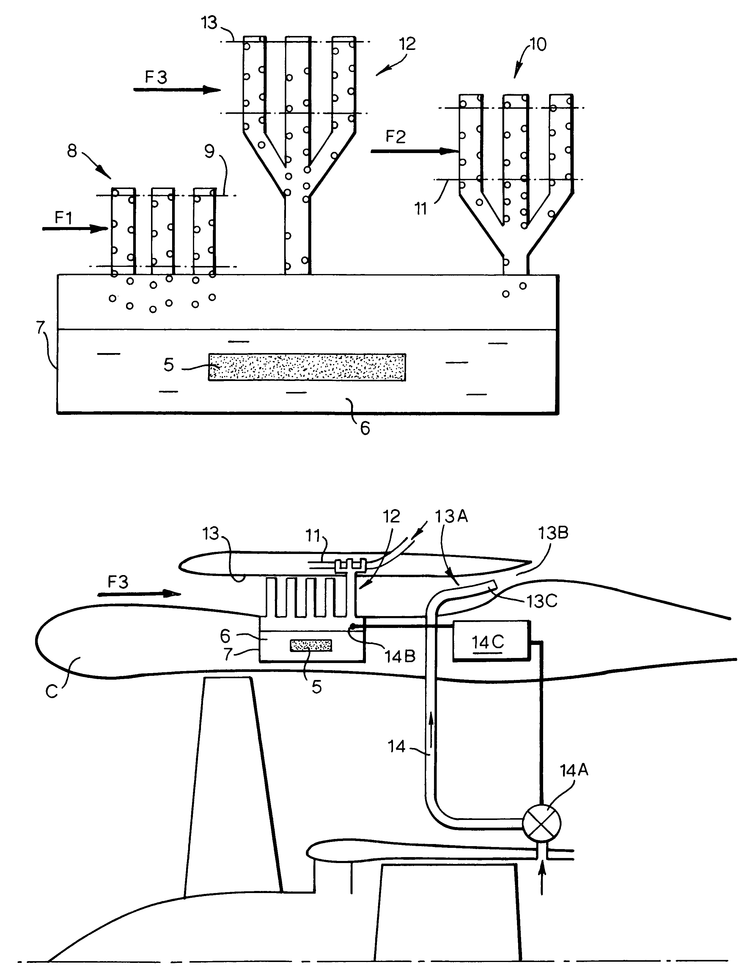
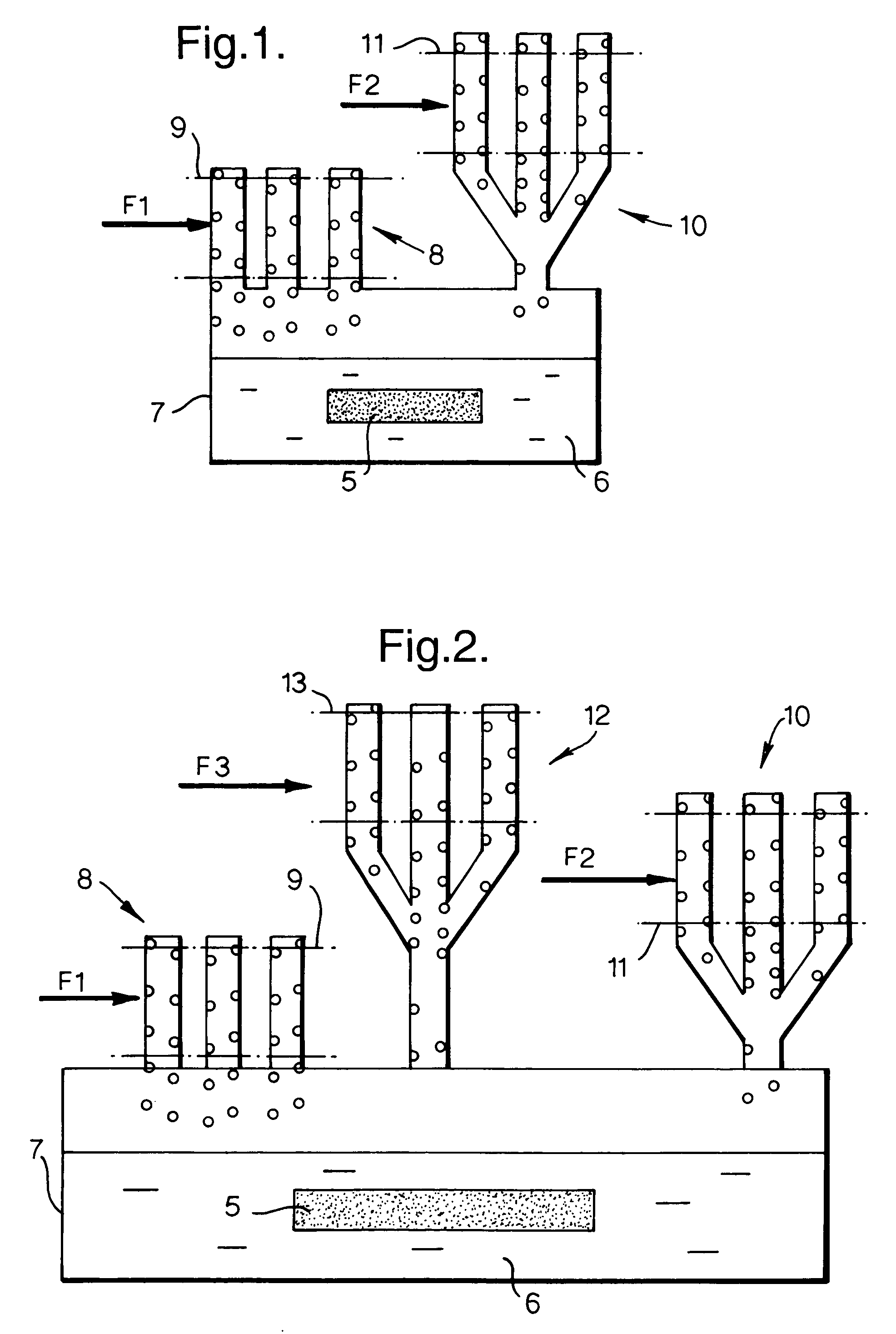
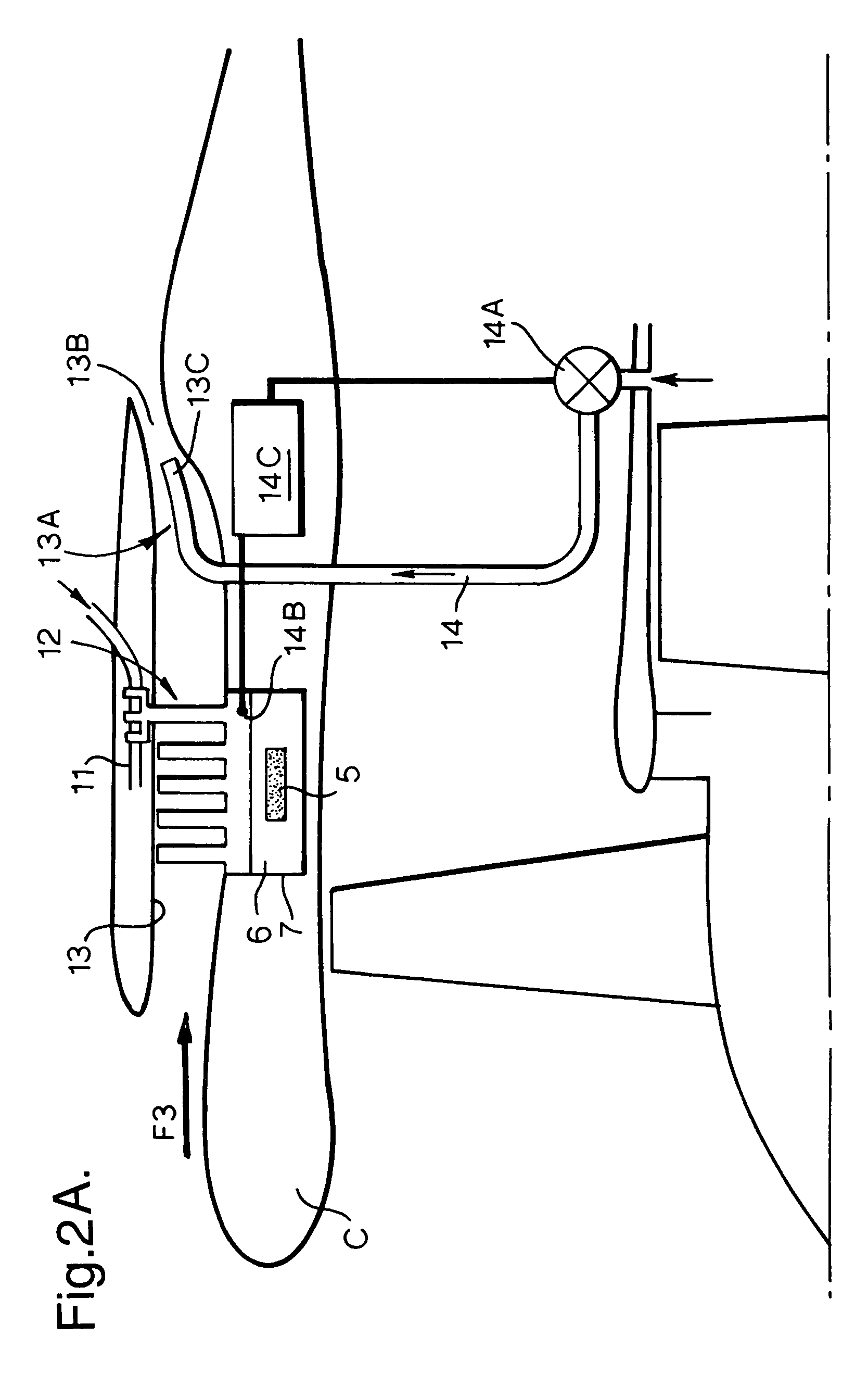
[0027]FIG. 1 illustrates a cooling system for power electronics of a gas turbine engine. The electronic devices are housed in a casing 5 immersed in a high electrical resistivity thermal transfer liquid 6 contained in a sealed reservoir 7. The liquid may comprise water or preferably an electrically insulating liquid such as Fc77 produced by Minnesota Mining and Manufacturing Company of St. Paul, Minn., U.S.A. A first heat exchanger 8 is formed integrally with the reservoir 7 and is disposed in a duct 9 through which compressed air derived from the fan or low pressure compressor of the engine may flow in the direction of arrow F1. A second heat exchanger 10 is also connected to the chamber 7 and is disposed in a duct 11 through which engine fuel may flow in the direction of arrow F2.

[0028]The electronic components contained in the housing 5 may serve to control supply of power from the aircraft to the engine to start the engine and from the engine to the aircraft for operation of air...


PUM


Abstract

Apparatus for maintaining the temperature of a component of a gas turbine engine below a predetermined maximum working temperature comprises a reservoir for a cooling fluid having a boiling point below the working temperature and in which the component is immersed or with which it is in contact. At least two heat exchangers are associated with the reservoir and operable to effect condensation of vaporised cooling fluid and return of same to the reservoir. Preferably the apparatus is a closed system incorporating three heat exchangers respectively adapted to effect heat exchange with engine fuel, compressed air derived from a fan or low pressure compressor of the engine and ambient air. Means may advantageously be provided to ensure return of condensed cooling fluid to the reservoir when the attitude of the reservoir is altered as a result of aircraft maneuvers.

Description

[0001]This application is a divisional of Ser. No. 10 / 419,254 filed on Apr. 21, 2003, now U.S. Pat. No. 6,931,834.FIELD OF THE INVENTION[0002]This invention relates to cooling systems and is particularly, but by no means exclusively applicable to cooling of electronic components or of fuel in gas turbine aircraft engines. The invention may also be applied to marine, rail, road or other vehicles or used in other situations.BACKGROUND OF THE INVENTION[0003]The primary power requirement of an aircraft is for thrust which is provided from its main engine or engines. In a large proportion of aircraft the main engine or engines are gas turbine engines. These conventionally also provide the majority of the secondary power of the aircraft which typically includes hydraulic power to move control surfaces and landing gear, electrical power for control systems, lighting and the like and compressed air power to provide environmental control within the aircraft. Typically the secondary power req...

Claims


Application Information

Patent Timeline
Patent Type & Authority Patents(United States)
IPC IPC(8): F02K3/02F28D15/02H01L23/427H05K7/20
CPCB64D2013/0614B64D2013/0659F28D15/02H01L23/427F28D15/0266H05K7/203H05K7/20318H01L2924/0002H01L2924/00
Inventor JONES, ALAN R
Owner ROLLS ROYCE PLC
Why Eureka
Try Eureka