Ultrasonic apparatus and method for measuring the concentration and flow rate of gas

a technology of ultrasonic transducers and gas concentration, which is applied in the direction of liquid/fluent solid measurement, using ultrasonic/ultrasonic/infrasonic waves, instruments, etc., can solve the problems of inability to accurately measure the concentration and flow rate of gas, the zero-cross time instant is not real propagation time, and the measurement error is strongly affected. to achieve the effect of accurate measurement of concentration and flow ra

Active Publication Date: 2007-05-08
TEIJIN LTD
View PDF8 Cites 71 Cited by
  • Summary
  • Abstract
  • Description
  • Claims
  • Application Information

AI Technical Summary

Benefits of technology

[0012]The object of the invention is to provide an ultrasonic apparatus and method for measuring concentration and flow rate of gas, which allow to accurately measure the concentration and flow rate of a sample gas without a complex signal processing and an additional hardware.

Problems solved by technology

However, the signal generated on the basis of the received ultrasonic waves always includes noise component, which makes difficult to determine the moment when ultrasonic waves are received by the ultrasonic transducer.
However, the obtained zero-cross time instant is not real propagation time of the ultrasonic waves.
In particular, when the concentration is measured, the measurement error is strongly affected by the difference between the real propagation time and the zero-cross time instant.
However, a hardware is necessary to sample the received ultrasonic waves and a complex signal processing is necessary to calculate the envelope curve based on the sampled waveform.
Therefore, according to the invention of JPP '422, it is difficult to provide a compact device with low cost.

Method used


Image

  • Ultrasonic apparatus and method for measuring the concentration and flow rate of gas
  • Ultrasonic apparatus and method for measuring the concentration and flow rate of gas
  • Ultrasonic apparatus and method for measuring the concentration and flow rate of gas

Examples


Embodiment Construction

[0074]A preferred embodiment of the present invention will be described below. In the embodiment described below, a sample gas is composed of a mixture of oxygen and nitrogen. However, the measurable sample gas is not limited to a sample gas of oxygen and nitrogen and the present invention can be supplied to a mixture including another gas.

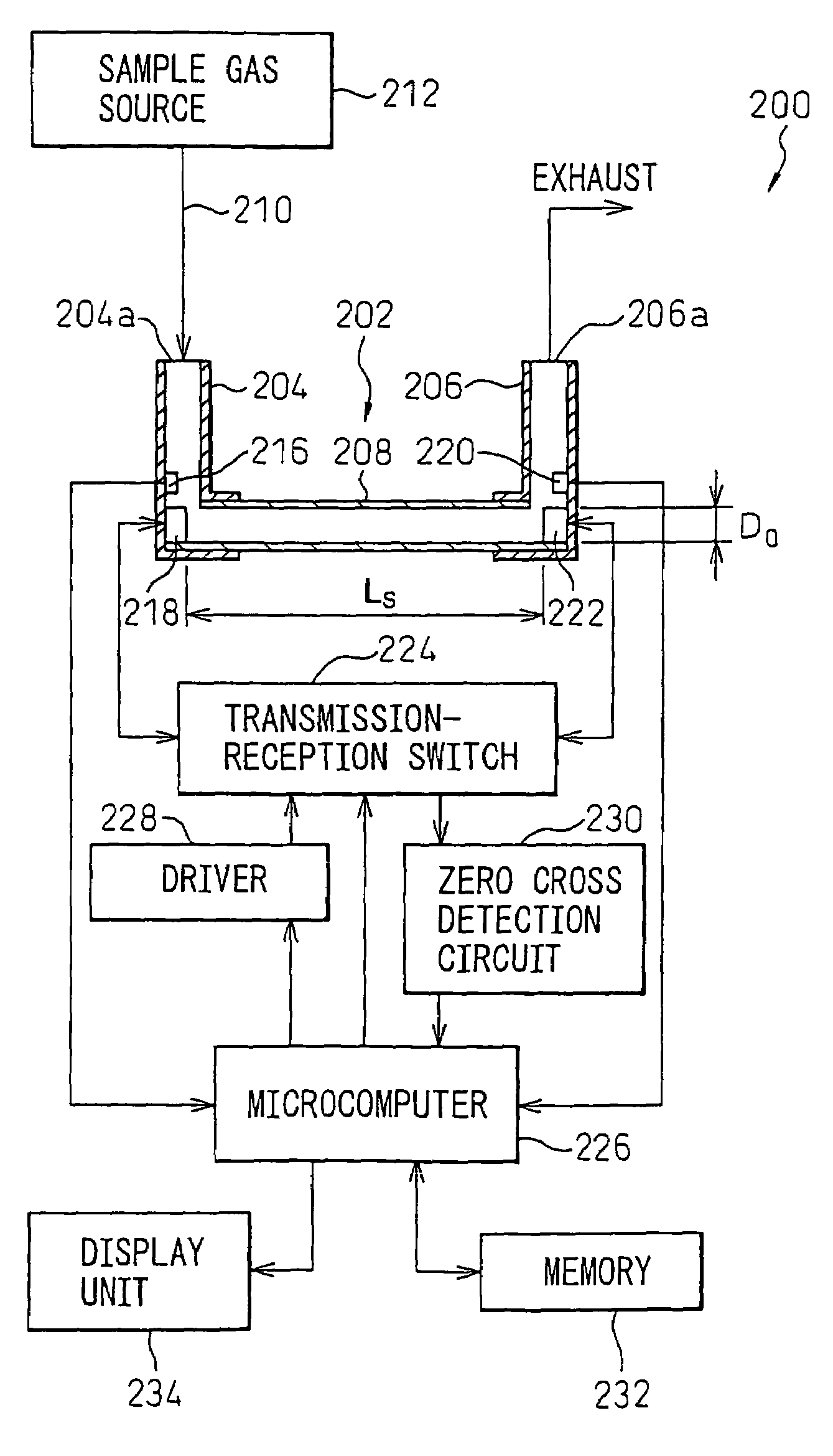
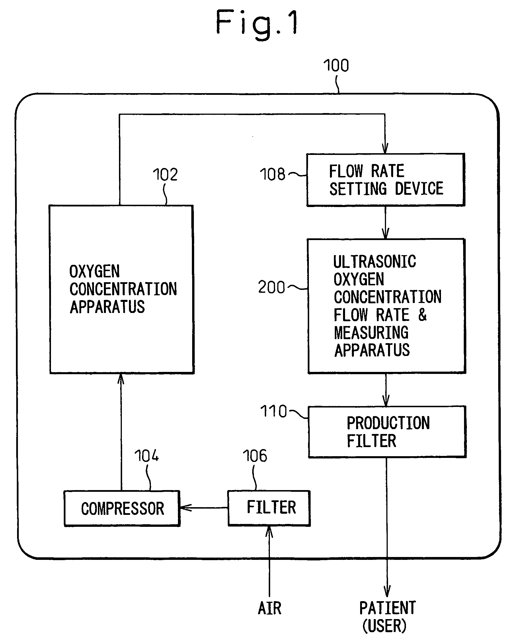
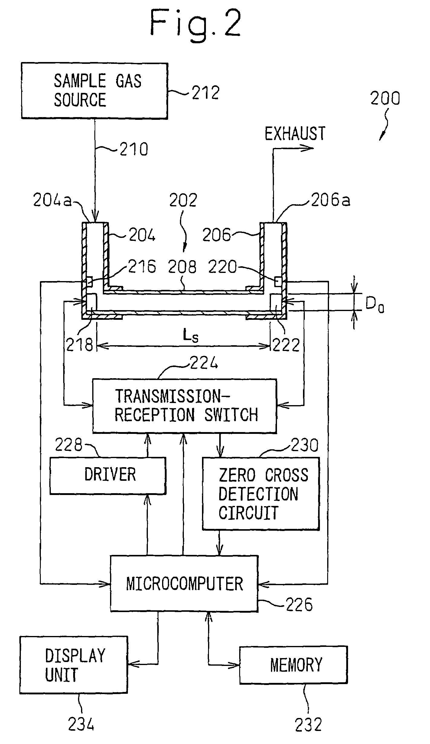
[0075]FIG. 1 shows a schematic diagram of an oxygen concentration system having an ultrasonic gas concentration and flow rate measuring apparatus according to a preferred embodiment of the present invention.

[0076]The apparatus 100 includes an oxygen concentration apparatus 102 which produces an oxygen enriched gas by removing nitrogen from the air supplied by a compressor 104 from the outside of the system through a filter 106. The oxygen enriched gas produced by the oxygen concentration apparatus 102 is supplied to an ultrasonic apparatus 200 of the present invention through a flow rate setting device 108, such as a pressure reduction valve. The ...


PUM

PropertyMeasurementUnit
velocityaaaaaaaaaa
velocityaaaaaaaaaa
velocityaaaaaaaaaa

Abstract

An ultrasonic apparatus measures the concentration and flow rate of a sample gas by calculating a possible propagation time range on the basis of the gas temperature, determining whether or not the phases at which two first trigger signals, respectively generated on the basis of forward and backward waveforms of the ultrasonic waves, coincide with each other, processing the zero-cross signals so that the phases coincide with each other, obtaining reference zero-cross time instant by calculating mean value of the forward and backward zero-cross time instants, obtaining an ultrasonic reception point by subtracting an integral multiple of the cycle of the ultrasonic waves so that the results of the subtraction falls into a possible propagation time range and estimating the ultrasonic propagation time on the basis of the ultrasonic reception point.

Description

TECHNICAL FIELD[0001]The invention relates to ultrasonic apparatus and method for measuring the concentration of oxygen gas in a sample gas and flow rate of the sample gas, which is supplied from an oxygen concentrator used for a medical purpose.BACKGROUND ART[0002]It is well known that the propagation velocity of ultrasonic waves through a sample gas is presented by a function of the concentration and the temperature of the sample gas. The velocity C(m / sec) of ultrasonic waves propagating through a stationary gas is presented by flowing equation (1) with mean molecular weight M and the temperature T(K).C=(κRT / M)1 / 2  (1)Where:[0003]κ: ratio of molecular specific heat at constant volume and molecular specific heat at constant pressure[0004]R: gas constant[0005]Therefore, measuring the velocity of ultrasonic waves C(m / sec) propagating through a sample gas and the temperature T(K) of the sample gas will provide the mean molecular weight M of the sample gas through a calculation. For ex...

Claims


Application Information

Patent Timeline
Patent Type & Authority Patents(United States)
IPC IPC(8): G01F1/66G01N29/07G01N29/22
CPCC21D7/00G01F1/668G01N29/07G01N29/222G01N2291/105G01N2291/02809G01N2291/02836G01N2291/02881G01F1/66G01N29/036
Inventor FUJIMOTO, NAOTOSHI
Owner TEIJIN LTD
Why Eureka
Try Eureka