
Continuous molding of fastener products

Inactive Publication Date: 2007-05-08
VELCRO IND BV
View PDF36 Cites 145 Cited by
  • Summary
  • Abstract
  • Description
  • Claims
  • Application Information

AI Technical Summary

Benefits of technology

[0097]The invention represents a significant improvement over conventional roll-forming machines and techniques, in many respects. By removing the mold cavities from the circumference of a single roll, the cavities can be advantageously circulated through cooling processes. The forming fastener elements are also afforded longer residence times, decreasing the rate at which they must be cooled and enabling greater crystallization during solidification. This can enable, in turn, lower cavity filling pressures even at relatively high production rates. In addition, the invention enables the use of solid rolls which more robustly resist bending loads than multi-plate rolls. The mold belt can be readily removed from the molding apparatus for cleaning and replacement, and is useful for forming, in one simple molding step, complete fastener products having a wide array of fastener elements all extending from a single, continuous, strip-form base. Many of the belt structures featured in the invention are inexpensive enough to produce that they may be considered disposable if their cavities become plugged.

Problems solved by technology

These crooks snag and retain loop fibers, for instance, to form a fastening, but can be challenging to mold in their fully functional form in non-opening mold cavities.
Thus, in prior implementations of the Fischer process the production speeds obtainable for a given diameter mold roll have been limited by the required “residence time” of the cooling fastener elements in their cavities to enable successful withdrawal.
Over-chilling the mold roll to reduce the required residence time can impede proper filling of the cavities by solidifying the resin as it is forced into the cavities.
Multi-plate mold rolls are more prone to bending deflection caused by molding pressures than solid rolls of similar diameter.
Such bending deflection can result in undesirable base thickness variation across the width of the fastener product at higher molding pressures.

Method used


Image

  • Continuous molding of fastener products
  • Continuous molding of fastener products
  • Continuous molding of fastener products

Examples


Embodiment Construction

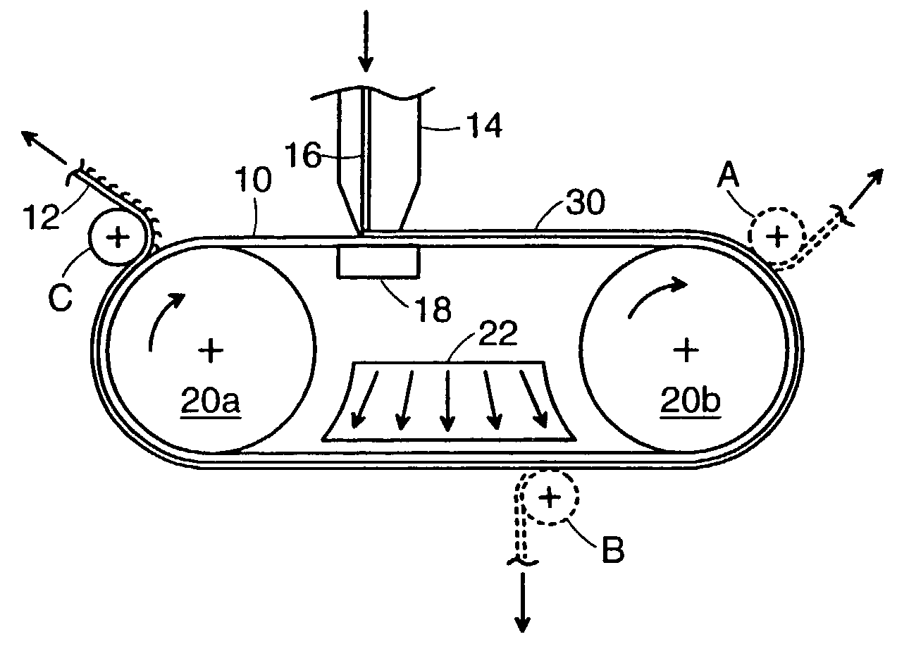
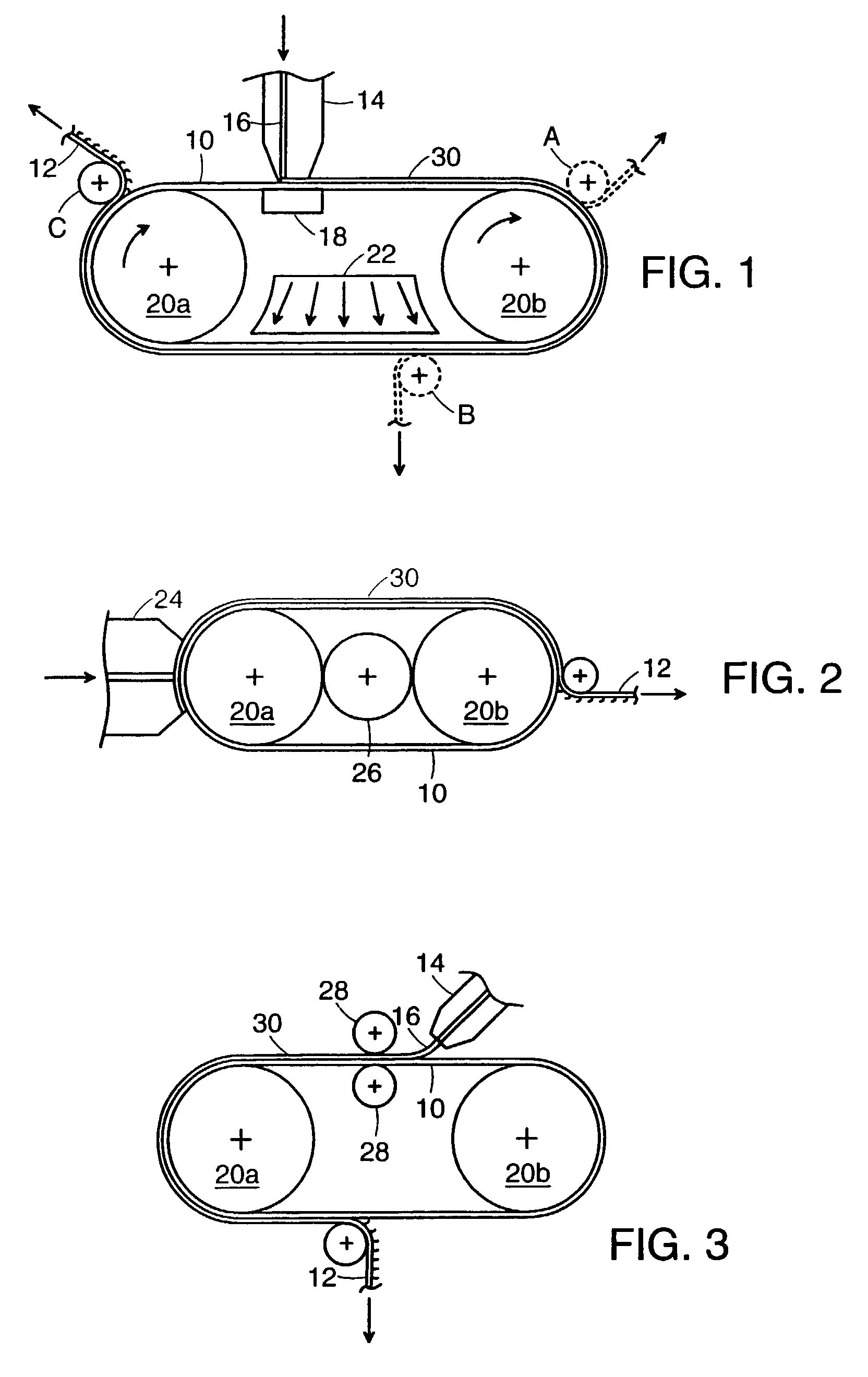
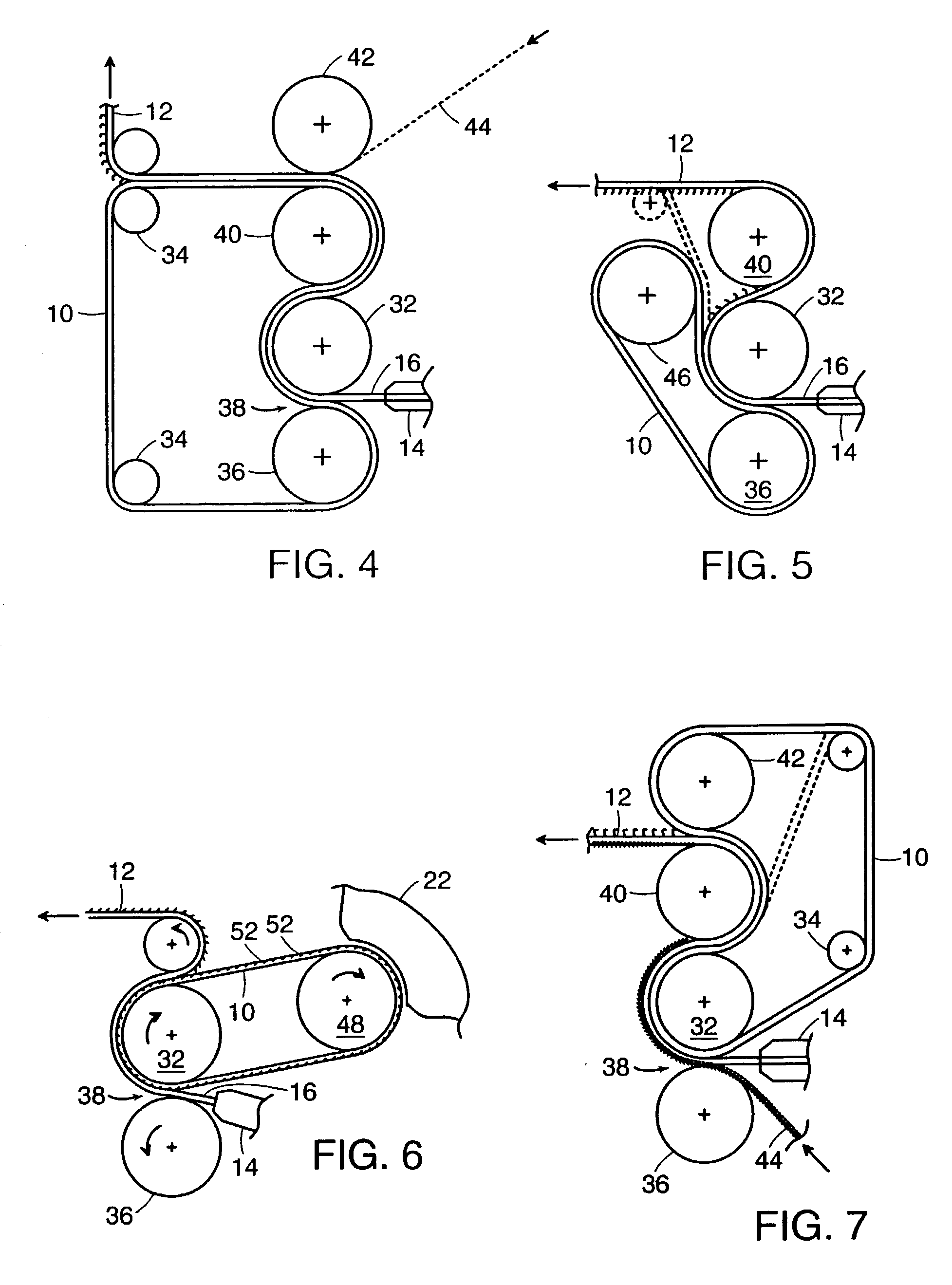
[0113]Each of the embodiments shown in FIGS. 1–7 have a recirculating mold belt 10 for continuously molding fastener products 12. The belts and rollers are not drawn to scale, and the thickness of the belt has been exaggerated for purposes of illustration.

[0114]In each of the illustrated arrangements, the product 12 formed is a sheet-form touch fastener product having a continuous, broad base of resin from which an entire two-dimensional array of miniature fastener elements extend, as shown in FIG. 26. The resin base of the fastener product, typically only about 0.002 to 0.020 inches thick and anywhere from one to 12 inches or more in width, is formed on one broad surface of belt 10 while the fastener elements are molded in individual mold cavities extending into the belt from the surface on which the base is formed. The arrangement and density of the cavities will vary between embodiments, but is generally the case that there will be between 50 and 2500 cavities per square inch of ...


PUM

PropertyMeasurementUnit
Lengthaaaaaaaaaa
Lengthaaaaaaaaaa
Thicknessaaaaaaaaaa

Abstract

Several methods and machines for continuously forming a fastener product having an array of fastener elements extending from a continuous, sheet-form base, employing a mold belt on which the sheet-form base of the product is formed and from which it is subsequently stripped. The belt defines an array of cavities extending from its outer surface, for molding either the array of fastener elements or an array of preform stems that are subsequently reformed into the fastener elements. In some cases the cavities are blind, such as for forming hook-type fastener elements; in other cases, the cavities extend through the belt, such as for forming mushroom-type fastener elements. Various belt constructions and fastener element shapes are also disclosed.

Description

CROSS-REFERENCE TO PENDING APPLICATIONS[0001]This application is a divisional (and claims the benefit of priority under 35 USC 120) of U.S. application Ser. No. 09 / 257,648, filed Feb. 25, 1999, now U.S. Pat. No. 6,432,339, which is a continuation-in-part of U.S. application Ser. No. 08 / 997,966, filed Dec. 24, 1997, now U.S. Pat. No. 6,099,289, which is a continuation-in-part of U.S. application Ser. No. 08 / 920,188, filed Aug. 25, 1997, now abandoned.BACKGROUND OF THE INVENTION[0002]This invention relates to the continuous molding of fastener products, such as those having a multiplicity of miniature fastening elements extending from a common sheet-form base.[0003]Touch fastener products have arrays of miniature fastener elements (for instance, hook-shaped or mushroom-shaped elements) extending from a common base. Typically, in order to be capable of engaging a loop fiber or another fastener element, these fastener elements have overhanging “crooks”, such as the hook portion of a hoo...

Claims


Application Information

Patent Timeline
IPC IPC(8): B29C41/28B29C43/48A44B18/00B29C33/30B29C33/38B29C43/22B29C43/46B29C45/00B29C45/26B29C48/07B29C48/35B29C59/02
CPCA44B18/0049B29C33/3857B29C41/28B29C43/222B29C43/46B29C45/0003B29C45/2673B29C47/32B29C47/885B29C59/025B29C33/302B29C2043/461B29C45/2675B29C47/0021B29C2043/023B29C2043/3678B29C2043/465B29L2031/729Y10S425/814B32B37/153B29C48/08B29C48/35B29C48/9145B29C48/07
Inventor JENS, STEPHEN C.CLUNE, WILLIAMPROVOST, GEORGE A.BABINEAU, JAMES W.
Owner VELCRO IND BV
Learn More