Harmonic termination circuit for medium bandwidth microwave power amplifiers

a technology of harmonic frequency termination and microwave power amplifier, which is applied in the direction of amplifiers, amplifiers with semiconductor devices only, amplifiers with semiconductor devices, etc., can solve the problems of difficult to adequately provide harmonic frequency termination, difficult to achieve harmonic frequency termination, and difficulty in adequately providing harmonic frequency termination, etc., to achieve low impedance, high impedance, and applicability.

Active Publication Date: 2007-05-08
HRL LAB
View PDF15 Cites 10 Cited by
  • Summary
  • Abstract
  • Description
  • Claims
  • Application Information

AI Technical Summary

Benefits of technology

[0013]In another aspect of the present invention a power combiner is provided having broadband termination of amplifier harmonics. A power combining network has a plurality of input ports and a power combined output port. Respective amplifiers are coupled to the input ports, each amplifier having an active device output. A pi network is configured to provide a low impedance at frequency bands above a frequency band of operation while allowing DC bias to be appliable to the active device output, wherein a respective pi network is coupled to each active device output. The pi network may include a low pass filter coupled to an active device drain, the low pass filter having an RF choke and a first capacitor, and a second capacitor coupled in parallel with the low pass filter, the second capacitor being valued to resonate with the RF choke to produce a high impedance at a desired frequency and a low impedance to at least a second harmonic of the desired frequency. The pi network may alternatively include a low pass filter coupled to an active device drain, the low pass filter having an RF choke and a first capacitor, and a series inductor capacitor resistor resonant circuit coupled in parallel with the low pass filter. The series inductor capacitor resistor resonant circuit has a resistor valued to provide a load to at least a second harmonic frequency of a desired frequency, a second capacitor being valued to resonate with the RF choke to produce a high impedance at the desired frequency and a low impedance to at least a second harmonic of the desired frequency, and an inductor being valued to resonate with the second capacitor at at least the second harmonic frequency of the desired frequency. The pi network may be formed by a combination of lumped circuit elements and distributed transmission lines.

Problems solved by technology

Such harmonics can be problematic for other networks operating adjacent to the network.
For larger power amplifier circuits that utilize a significant amount of space for output power combining and which also tend to be somewhat broadband in performance, it is difficult to adequately provide harmonic terminations because so much area is required for power combining.
The approaches work quite well but are somewhat narrowband (less than 20%) and do not lend itself to medium bandwidth applications such as is typical with the corporate feed scheme.

Method used


Image

  • Harmonic termination circuit for medium bandwidth microwave power amplifiers
  • Harmonic termination circuit for medium bandwidth microwave power amplifiers
  • Harmonic termination circuit for medium bandwidth microwave power amplifiers

Examples


Embodiment Construction

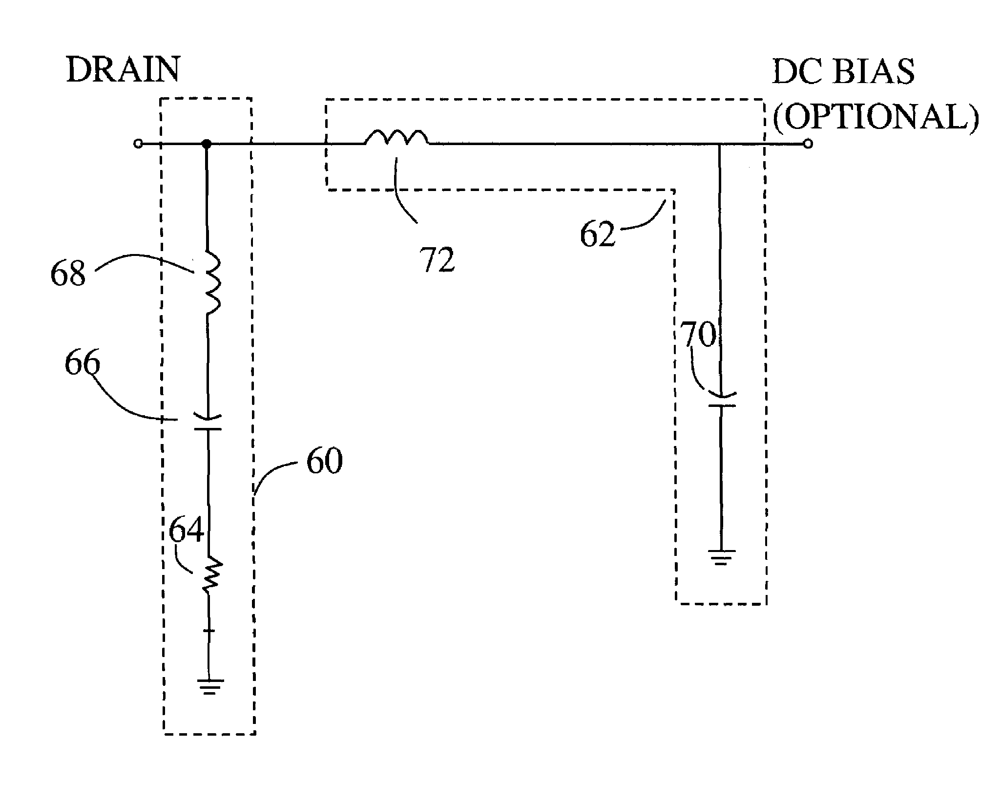
[0026]Those skilled in the art can appreciate that it is desirable to operate a power amplifier in a nonlinear region where the amplifier gain is compressed to achieve maximum output power and efficiency. In compression, the drain current can be represented as: Id(t)=Io+I1 cos(2πfot)+I2 cos(4πfot)+I3 cos(6πfot)+ . . . The components I2, I3 . . . are the harmonic current amplitudes. I1 is the fundamental frequency (fo) current amplitude. Io is the DC bias current amplitude.

[0027]The present invention not only provides a compact amplifier output bias circuit but one that can be used as a broadband harmonic termination.

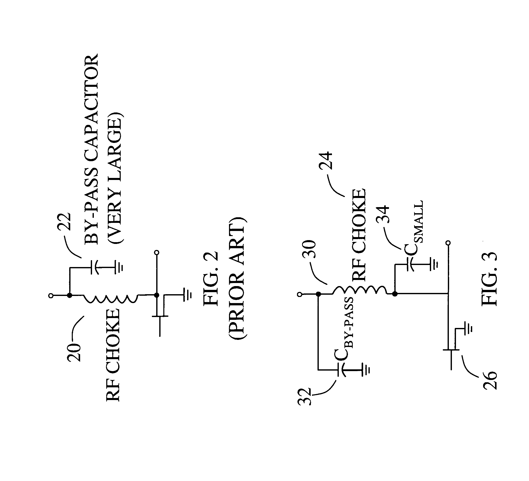
[0028]FIG. 3 shows an exemplary embodiment of harmonic termination circuit 24 in accordance with the present invention. The prior art low pass filter as shown in FIG. 2 is modified to a pi network to provide essentially a band pass response and to provide an effective low impedence (e.g., nearly a short circuit) at frequency bands above the frequency band of operation, i...


PUM


Abstract

A compact amplifier output bias circuit is used as a broadband harmonic termination. The bias circuit is adapted as a harmonic termination circuit to produce an effective low impedance or act as a load at the signal harmonic frequencies while having the capability of supplying DC power to the amplifier stage, optionally, if needed. A pi network is coupled to an active device output and provides a low impedance at frequency bands above a frequency band of operation while allowing DC bias to be appliable to the active device output.

Description

STATEMENT REGARDING FEDERALLY SPONSORED RESEARCH OR DEVELOPMENT[0001]This invention was made with U.S. Government support under Contract No. N00014-03-C-0241 awarded by the Office of Naval Research. The U.S. Government has certain rights to this invention.BACKGROUND OF THE INVENTION[0002]This invention relates to the field of power amplifiers, and, more particularly, to microwave power amplifier harmonic frequency terminations.[0003]Modern power amplifier architectures, such as balanced, push-pull, single ended and low noise power amplifiers, including microwave monolithic integrated circuit (MMIC) power amplifiers, have an increasing need for both linearity and power added efficiency.[0004]Corporate feed networks, such as that shown in FIG. 1, are typically used to combine the outputs from many devices by terminating each device in the optimum load impedance for maximum power transfer. In corporate feed network 10 there are shown active device pairs 12a, 12b and 12c, 12d, and which...

Claims


Application Information

Patent Timeline
Patent Type & Authority Patents(United States)
IPC IPC(8): H01P5/12
CPCH01P5/12H03F3/604
Inventor ELLIS, GRANT ANDREWMOON, JEONG-SUNKURDOGHLIAN, ARA K.
Owner HRL LAB
Why Eureka
Try Eureka