Electrochromic element drive control circuit

a technology of drive control circuit and electrochromic element, which is applied in the direction of vehicle components, instruments, computing, etc., can solve the problems of increasing the cost, increasing the cost, and generally not optimizing the integration of the drive circuit components while meeting the heat dissipation requirements. , to achieve the effect of dissipating thermal energy outside of the chip

Inactive Publication Date: 2007-05-08
GENTEX CORP
View PDF15 Cites 90 Cited by
  • Summary
  • Abstract
  • Description
  • Claims
  • Application Information

AI Technical Summary

Benefits of technology

[0007]According to another aspect of the present invention, a control circuit is provided for controlling an electrochromic element. The control circuit includes an integrated circuit chip, and drive circuitry substantially integrated in the integrated circuit chip for driving the electrochromic element. The drive circuitry includes a current control circuit configured ...

Problems solved by technology

The use of the series pass transistor to drop the voltage to an EC operating level generally results in power dissipation that is converted to thermal energy.
Excessive thermal energy generated in the series transistor within the mirror housing may damage the drive circuit and other electronic circuitry, and thus temperature tolerant components are generally required which adds to the cost.
However, many of the components of the drive circuit in conventional electrochromic mirror ap...

Method used


Image

  • Electrochromic element drive control circuit
  • Electrochromic element drive control circuit
  • Electrochromic element drive control circuit

Examples


Embodiment Construction

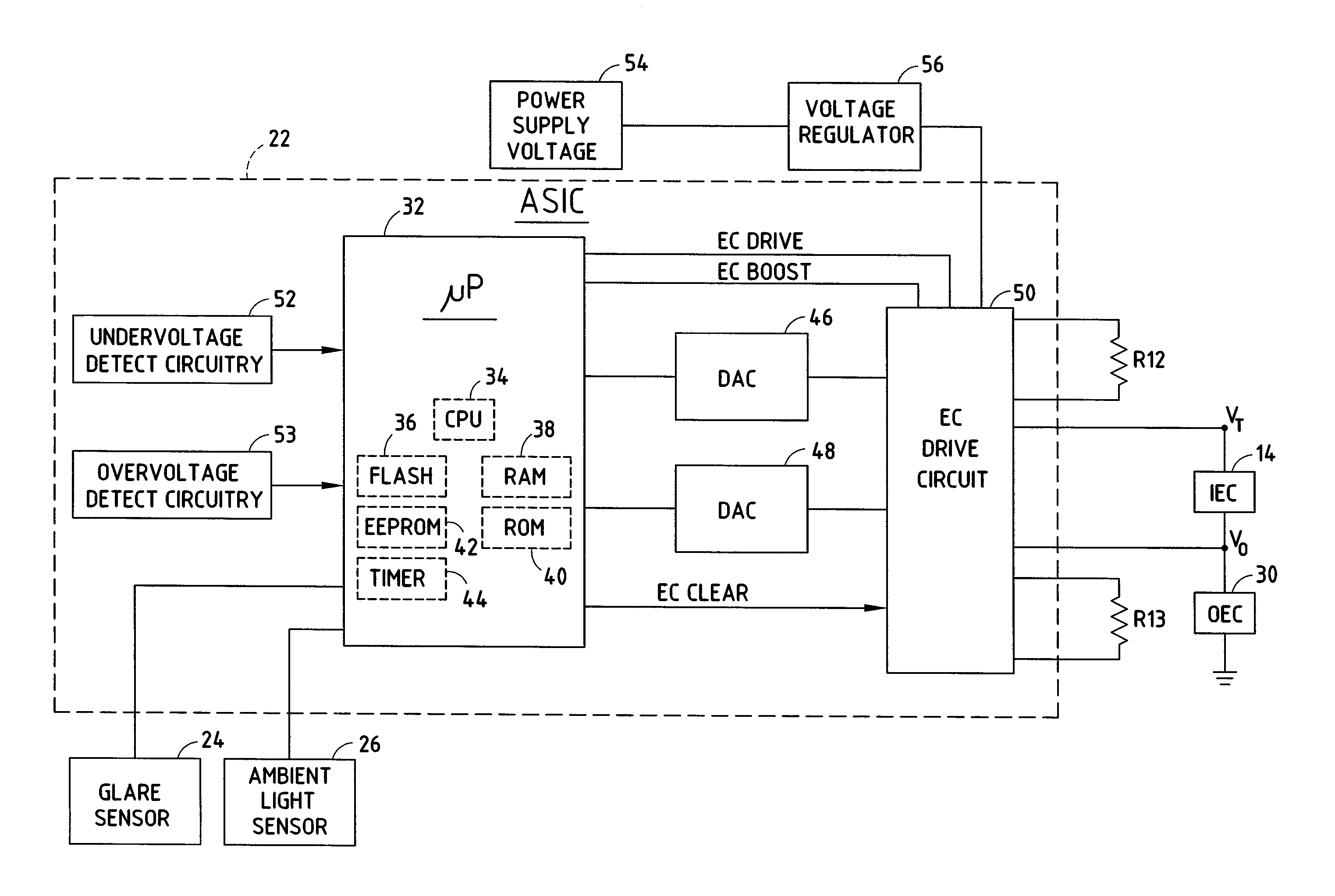
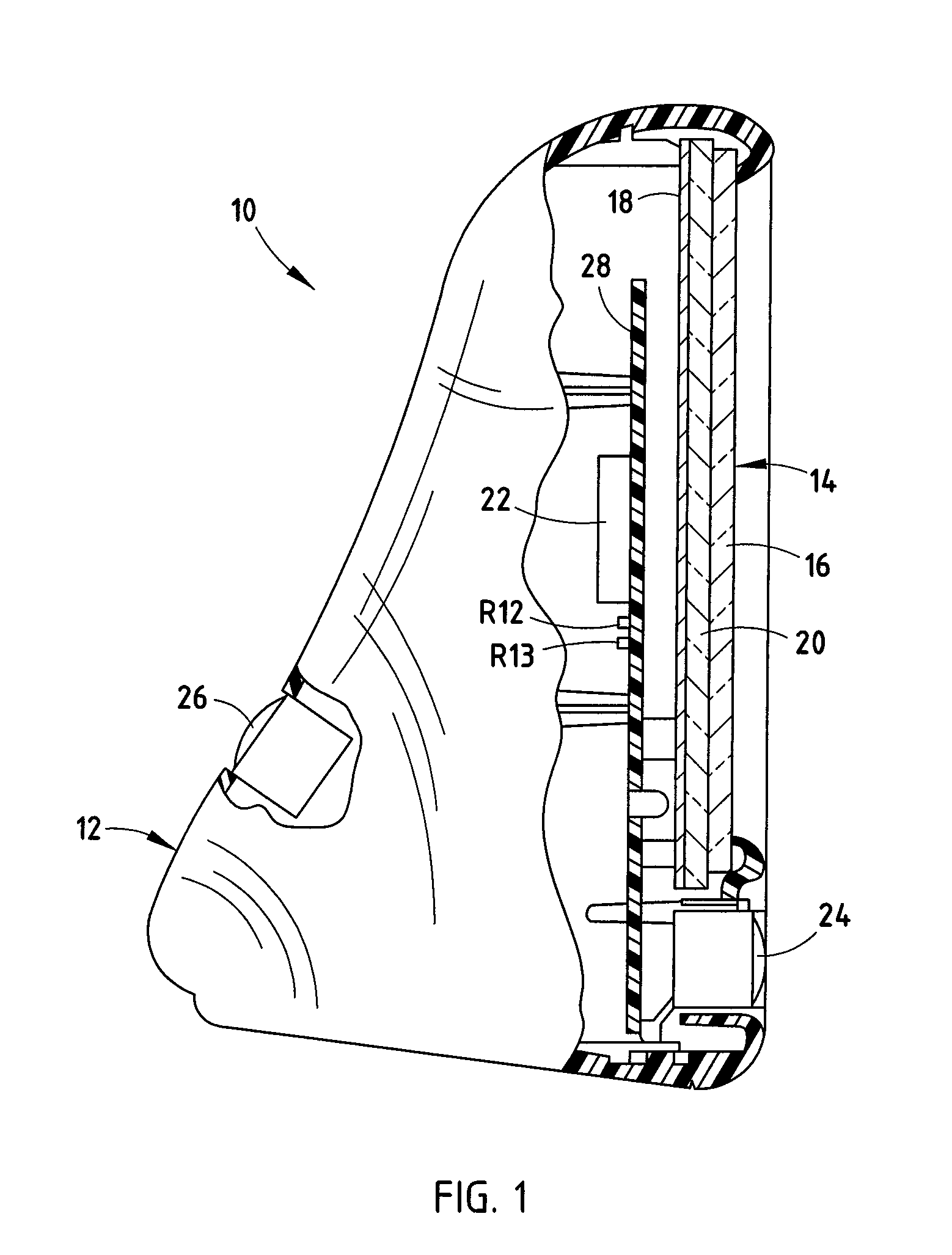
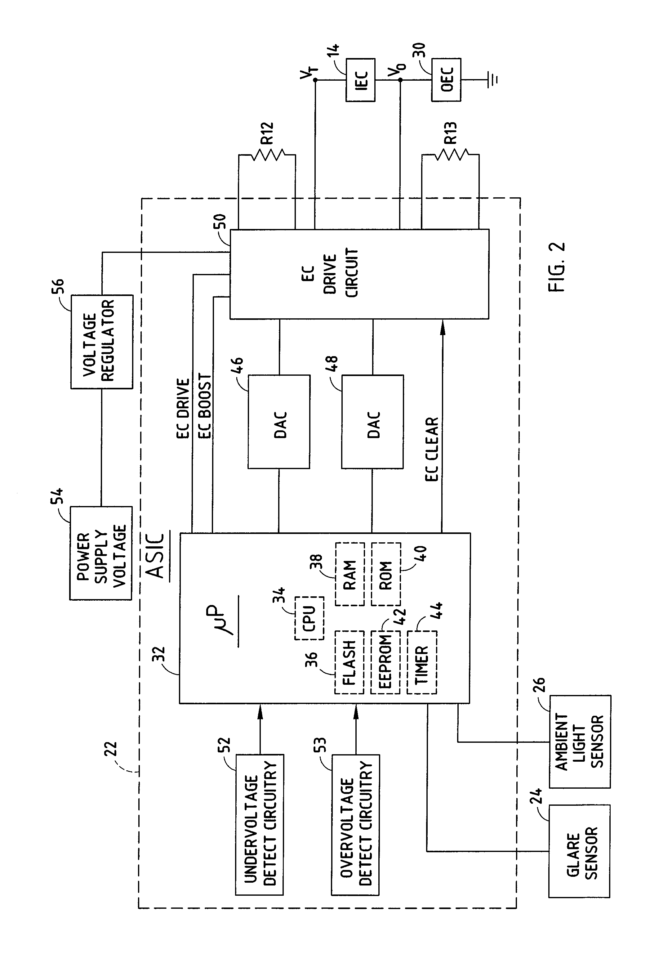
[0021]Referring to FIG. 1, a mirror assembly is shown having a housing 12 and a mirror subassembly 14 (referred to herein as “mirror 14”) mounted in an opening in the front face of the housing 12. The mirror 14 is an electrochromic mirror having an electrochromic element that is electrically controllable to adjust reflectance so as to control the amount of glare reflected to a viewer (e.g., driver of a vehicle). The mirror assembly 10 shown is generally referred to as an inside rearview mirror which is intended to be mounted within the passenger compartment of a vehicle. The vehicle may also be equipped with one or more outside rearview mirrors each having an electrochromic element. The present invention employs controls, including an electrochromic drive circuit, that control the inside electrochromic element and the outside electrochromic element(s).

[0022]The mirror 14 is shown having a first transparent substrate 16 arranged in front of a second substrate 20, which may also be tr...


PUM


Abstract

A drive control circuit for controlling an electrochromic element is substantially integrated into an integrated circuit, with the exception of resistive elements for dissipating heat away from the integrated circuit. The drive control circuit includes a current regulator for generating a select one of at least two discrete amounts of current to drive the electrochromic element. Further, a control system individually controls a plurality of electrochromic elements and includes shunts coupled in parallel with the individual electrochromic elements. The control system controls the ratio of the reflectance of the individual electrochromic elements as a function of sensed glare.

Description

BACKGROUND OF THE INVENTION[0001]The present invention generally relates to electrochromic elements, such as electrochromic mirrors, and, more particularly relates to a drive control circuit for driving one or more electrochromic elements.[0002]Electrochromic elements (EC) are increasingly employed for use in electrochromic mirrors, window systems, and other electronic glare control applications, particularly for use on automotive vehicles. In automotive applications, an electrochromic element is commonly employed in the inside rearview mirror for use in varying the reflectance of the mirror to automatically control glare from external light sources. In addition, it is known to employ a plurality of electrochromic elements in a vehicle, including electrochromic elements in the inside rearview mirror and one or more outside rearview mirrors. The reflectance of an electrochromic element generally is a function of the voltage applied to the electrochromic element as, for example, as de...

Claims


Application Information

Patent Timeline
IPC IPC(8): G09G3/38G02B27/00G09G3/19G09G5/00B60R1/08G02B5/136G09G3/12
CPCB60R1/088
Inventor TURNBULL, ROBERT R.SCHMIDT, DAVID J.
Owner GENTEX CORP
Why Eureka
Try Eureka