Path timing detection method, path timing detection apparatus, and adaptive array antenna system

Inactive Publication Date: 2007-05-08
NEC CORP
View PDF15 Cites 2 Cited by
  • Summary
  • Abstract
  • Description
  • Claims
  • Application Information

AI Technical Summary

Benefits of technology

[0018]In view of the above-described problems, an object of the present invention is to provide a path timing detection method for an adaptive array antenna system realizing improved path timing detection characteristics and high-quality demodulation results by simple processing, and a path timing detection apparatus and an adaptive array antenna system in which processing according to the path timing detection method is performed.
[0019]Another object of the present invention is to provide a path timing detection method for an adaptive array antenna system realizing improved path timing detection characteristics and high-quality demodulation results in such a manner that delay profiles are formed on a beam-by-beam basis from signals obtained by multibeam reception and having an improved SINR, and path timings are detected with reliability from chip timings in delay profiles with respect to all beams while the influence of path spreading is eliminated, and a path timing detection apparatus and an adaptive array antenna system in which processing according to the path timing detection method is performed.

Problems solved by technology

However, user signals access a base station simultaneously with a desired user signal and interfere with the desired user signal.
However, this method only reduces the spread of each of the peak level and the noise level of delay profiles with respect to paths and does not immediately improve the SINR (the difference between the peak level and the noise level).
Thus, there is a limit to the improvement in characteristics based on delay profile combining.

Method used


Image

  • Path timing detection method, path timing detection apparatus, and adaptive array antenna system
  • Path timing detection method, path timing detection apparatus, and adaptive array antenna system
  • Path timing detection method, path timing detection apparatus, and adaptive array antenna system

Examples


Embodiment Construction

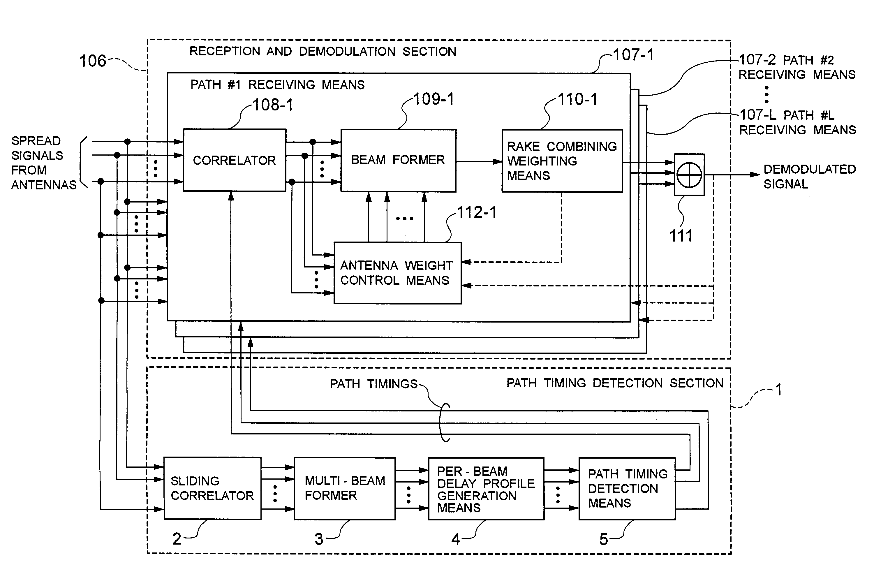
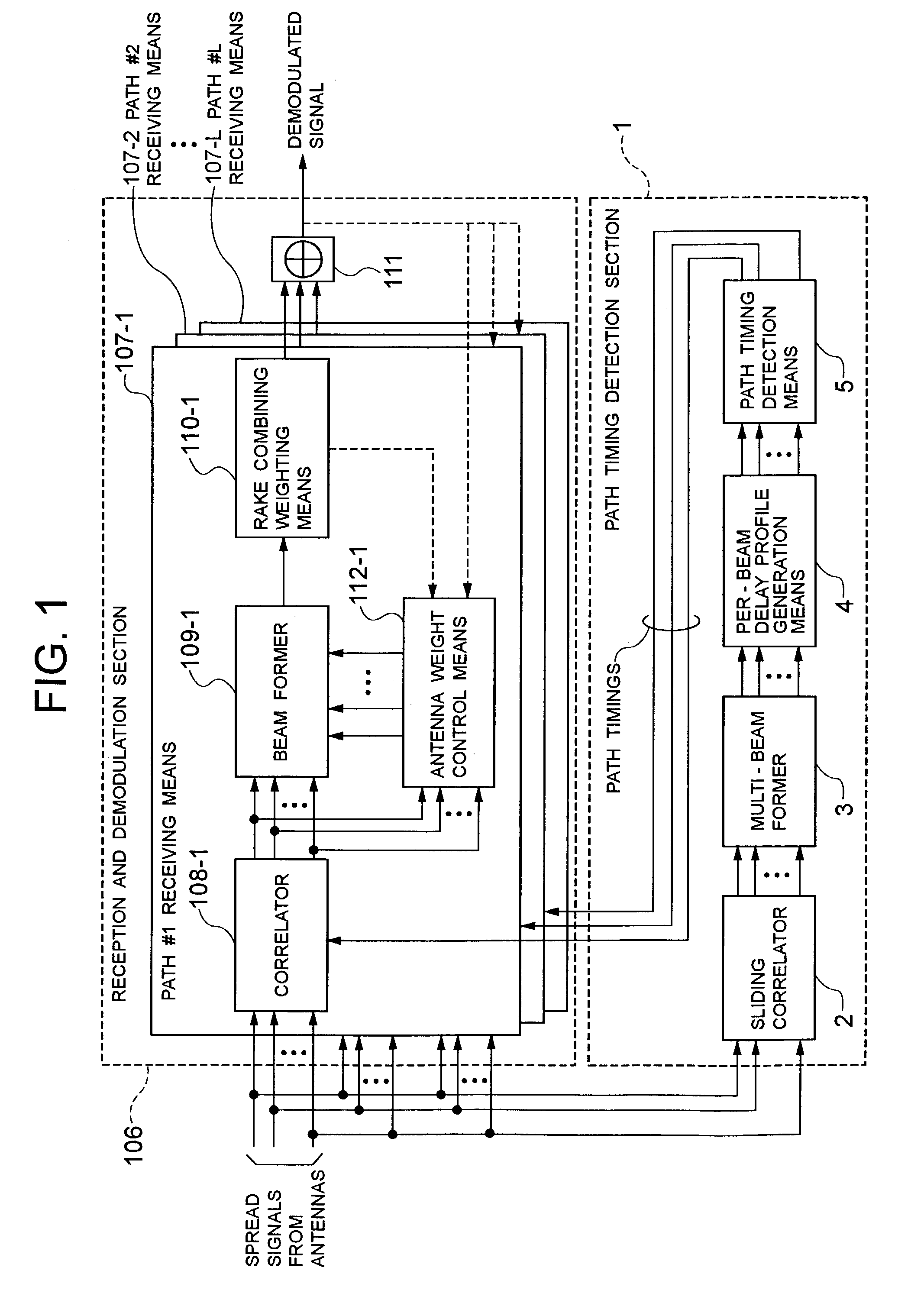
[0045]FIG. 1 is a diagram showing an embodiment of the present invention. A path timing detection apparatus and an adaptive array antenna system according to the embodiment of the present invention have a path timing detection section 1 and a reception and demodulation section 106. The path timing detection section 1 has a sliding correlator 2, a multibeam former 3, a per-beam delay profile generation means 4, and a path timing detection means 5.

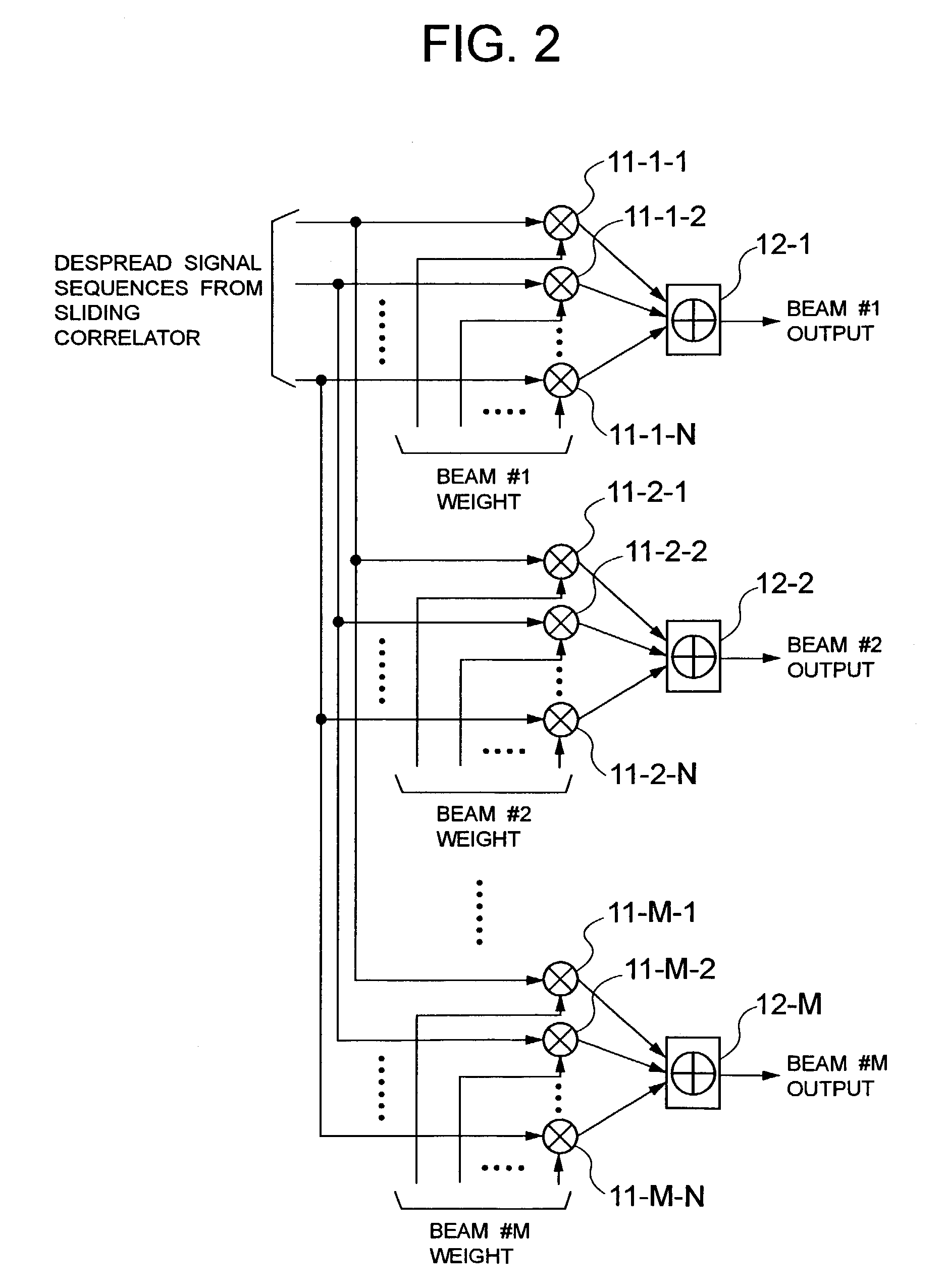
[0046]The sliding correlator 2 despreads signals from respective antennas at a resolution of 1 / NR (NR: an integer equal to or larger than 1) of the chip period over a plurality of chip timings, and outputs despread signal sequences. The multibeam former 3 forms a plurality of directional beams from outputs of the sliding correlator 2, and outputs signal sequences of the respective beams.

[0047]FIG. 2 is a diagram showing the configuration of the multibeam former 3. The multibeam former 3 has multipliers 11-1-1 to 11-1-N, . . . , 11-M-1 to 11-...


PUM


Abstract

To provide a path timing detection method for an adaptive array antenna system realizing improved path timing detection characteristics and high-quality demodulation results by simple processing. A sliding correlator despreads signals from antennas over a plurality of chip timings. A multibeam former forms a plurality of directional beams from outputs of the sliding correlator. A per-beam delay profile generation means generates a delay profile averaged in a certain cycle with respect to each beam by using the signal sequences of the beams from the multibeam former. A path timing detection means detects path timings one after another from the generated delay profiles with respect to the respective beams by using a minimum selection timing interval centered on a chip timing already selected as a path timing and a minimum selection beam interval centered on the beam having the chip timing already selected.

Description

BACKGROUND OF THE INVENTION[0001]1. Field of the Invention[0002]The present invention relates to path timing detection in an adaptive array antenna system and, more particularly, to a path timing detection method, a path timing detection apparatus and an adaptive array antenna system in which code division multiple access (CDMA) signals are received by an array antenna and path timings are detected by using signals obtained by multibeam reception.[0003]2. Description of the Related Art[0004]Code division multiple access (CDMA) has the potential for increasing the number of subscribers in a communication system and is therefore considered a promising wireless access method for mobile communication cellular system. However, user signals access a base station simultaneously with a desired user signal and interfere with the desired user signal. A technique using an adaptive array antenna is used to eliminate such interference in a spatial region.[0005]In an adaptive array antenna system...

Claims


Application Information

Patent Timeline
IPC IPC(8): H04B1/00H03D1/04H04B1/707H04B1/7113H04B1/7117H04B1/712H04B7/08H04B7/26H04W16/28H04W56/00H04W76/02
CPCH04B1/7095H04B1/7113H04B7/0897H04B7/0842H04B1/7117
Inventor YOSHIDA, SHOUSEI
Owner NEC CORP
Why Eureka
Try Eureka