Synchronization circuit and synchronization method, wireless communication device and wireless communication method, and computer program

a technology of synchronization circuit and synchronization method, applied in the direction of amplitude demodulation, wireless commuication services, baseband system details, etc., can solve the problems of increasing the manufacturing cost of the system and power consumption, and affecting the accuracy of timing detection

Inactive Publication Date: 2010-03-11
SONY CORP
View PDF6 Cites 44 Cited by
  • Summary
  • Abstract
  • Description
  • Claims
  • Application Information

AI Technical Summary

Benefits of technology

[0055]According to the fourteenth embodiment of the invention, accuracy in timing detection may be improved by assigning multiple synchronization candidates arranged in the temporal axis direction to a single reception branch and selecting more suitable reception timing from the synchronization candidates greater in number than that of the reception branches.

Problems solved by technology

Mistiming in FFT operations may cause intersymbol interference and symbol rotation, which may result in impaired reception performance.
Autocorrelation is useful even in the presence of reflection or fading, but may disadvantageously correlate data and even noise other than the preamble.
However, the circuit for calculating crosscorrelation values is significantly large in scale, thereby increasing the manufacturing cost of the system and power consumption.
It is clear, however, that accuracy in synchronization timing is low and reception performance may be impaired by inter symbol interference or symbol rotation.

Method used


Image

  • Synchronization circuit and synchronization method, wireless communication device and wireless communication method, and computer program
  • Synchronization circuit and synchronization method, wireless communication device and wireless communication method, and computer program
  • Synchronization circuit and synchronization method, wireless communication device and wireless communication method, and computer program

Examples


first embodiment

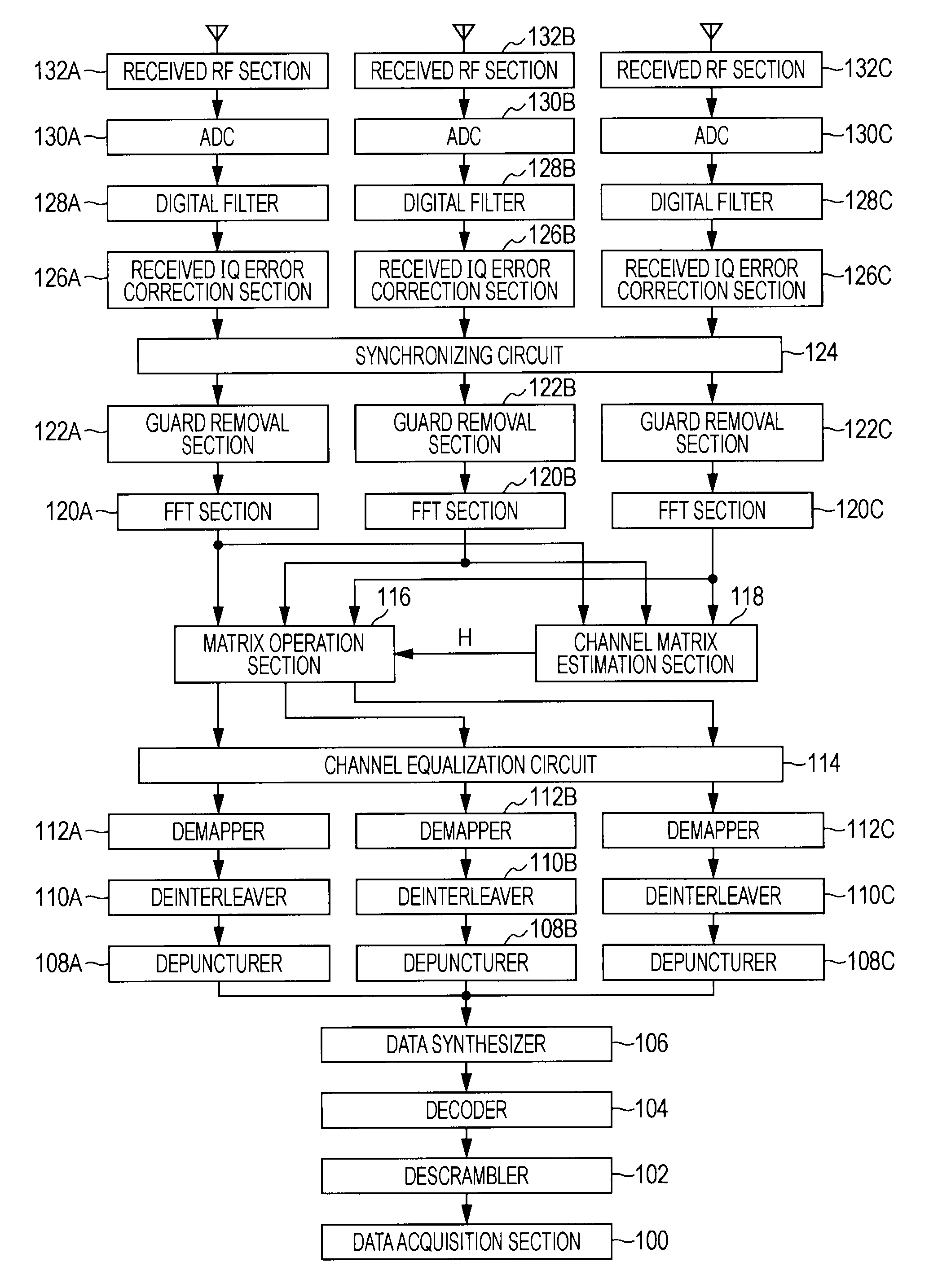
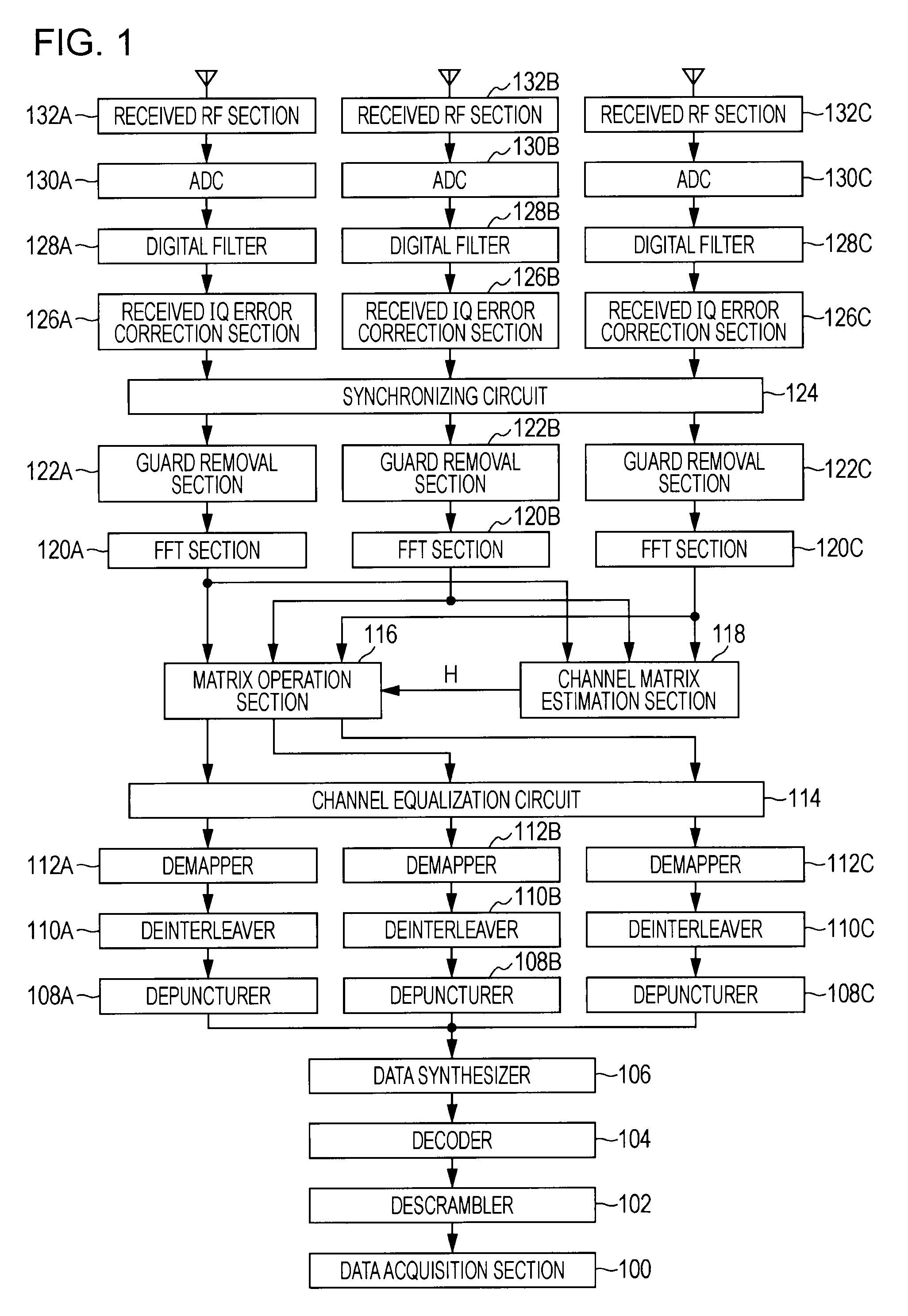
[0108]FIG. 4 shows configuration (first embodiment) of inside of the synchronizing circuit 124 and its peripheral circuit. In the illustrated example, three reception branches are provided for ease of description.

[0109]In the synchronizing circuit 124, a coarse synchronizing circuit 40 for determining the rough reception timing (temporary reception timing) using the reception L-STF portion is provided for each reception branch. Reception digital signals subject to IQ error correction in each of the reception branches is input into the coarse synchronizing circuit 40.

[0110]The synchronizing circuit 124 creates multiple synchronization candidates centering on the temporary reception timing obtained from the coarse synchronizing circuit 40 and then assigns the candidates to each of the reception branches. In particular, suppose that the time of the temporary reception timing determined by the L-STF is t, a first synchronization candidate timing control section 41 sends the L-LTF receiv...

second embodiment

[0130]FIG. 9 illustrates a configuration of an inside of the synchronizing circuit 124 and its peripheral circuit (second embodiment) in which the synchronization candidate is selected based on the amount of phase rotation of the L-LTF portion after the FFT operation is performed with multiple synchronization candidates from the original signal. In the illustrated example, three reception branches are provided for ease of description.

[0131]A coarse synchronizing circuit 90 for determining the rough reception timing (temporary reception timing) using the reception L-STF portion is provided in the synchronizing circuit 124. Received digital signals subject to IQ error correction in each of the reception branches are input into the coarse synchronizing circuit 90. The coarse synchronizing circuit 90 is configured as shown, for example, in FIG. 5 or FIG. 7 (as described above).

[0132]The synchronizing circuit 124 creates multiple synchronization candidates centering on the temporary rece...

third embodiment

[0140]FIG. 10 illustrates a configuration of an inside of the synchronizing circuit 124 and its peripheral circuit (third embodiment) in which processes before the decoder104 has been completed for the FFT operation output of each of the multiple synchronization candidates and the synchronization candidates are evaluated and selected based on the decoded result. In the illustrated example, three reception branches are provided for ease of description.

[0141]In the synchronizing circuit 124, a coarse synchronizing circuit 100 for determining the rough reception timing (temporary reception timing) using the reception L-STF portion is provided for each reception branch. Received digital signals subject to IQ error correction in each of the reception branches are input into the coarse synchronizing circuit 1000. The coarse synchronizing circuit 1000 is configured a shown, for example, in FIG. 5 or FIG. 7 (as described above).

[0142]The synchronizing circuit 124 creates multiple synchroniz...


PUM


Abstract

A synchronizing circuit comprising: a coarse synchronizing circuit which determines temporary reception timing using a preamble consisting of a repetition of known training signals added to a reception packet; a synchronization candidate timing control section which sets up multiple synchronization candidates based on the temporary reception timing and controls synchronization of received signal s in each of the multiple synchronization candidates; a signal quality monitoring section which monitors signal quality of the received signal s synchronized in each of the multiple synchronization candidates; and a synchronization candidate selecting section which selects one of the synchronization candidates as a final reception timing based on a monitoring result of the signal quality in the signal quality monitoring section.

Description

BACKGROUND OF THE INVENTION[0001]1. Field of the Invention[0002]The present invention relates to a synchronization circuit and a synchronization method in which a packet is detected using a preamble of a packet received from a communication partner and synchronization processing is performed. The invention also relates to a wireless communication device and a wireless communication method in which a reception operation is performed on the basis of a synchronization result using the packet preamble, and a computer program. More particularly, the invention relates to a synchronization circuit and a synchronization method, a wireless communication device and a wireless communication method and a computer program that detect exact reception timing using the preamble of a packet in a receiver with a plurality of reception branches.[0003]More particularly, the invention relates to a synchronization circuit and a synchronization method, a wireless communication device and a wireless commun...

Claims


Application Information

Patent Timeline
Patent Type & Authority Applications(United States)
IPC IPC(8): H04L27/06H04L7/00H04J3/06
CPCH04L5/0023H04L7/042H04L25/0204H04L2025/03426H04L27/2675H04L2025/03414H04L27/2655
Inventor TAKAHASHI, HIROAKITAKANO, HIROAKI
Owner SONY CORP
Why Eureka
Try Eureka