System and method for vascular border detection

a technology of vascular border and detection system, applied in the field of vascular images, can solve the problems of poor quality, time-consuming process, and process difficulty

Active Publication Date: 2007-05-08
THE CLEVELAND CLINIC FOUND
View PDF51 Cites 211 Cited by
  • Summary
  • Abstract
  • Description
  • Claims
  • Application Information

AI Technical Summary

Problems solved by technology

This is a very time consuming process.
Furthermore, this process is made more difficult when multiple images are being analyzed (e.g., to recreate a 3D vascular image, etc.) or the images are of poor quality (e.g., making the boundaries more difficult to see).

Method used


Image

  • System and method for vascular border detection
  • System and method for vascular border detection
  • System and method for vascular border detection

Examples


first embodiment

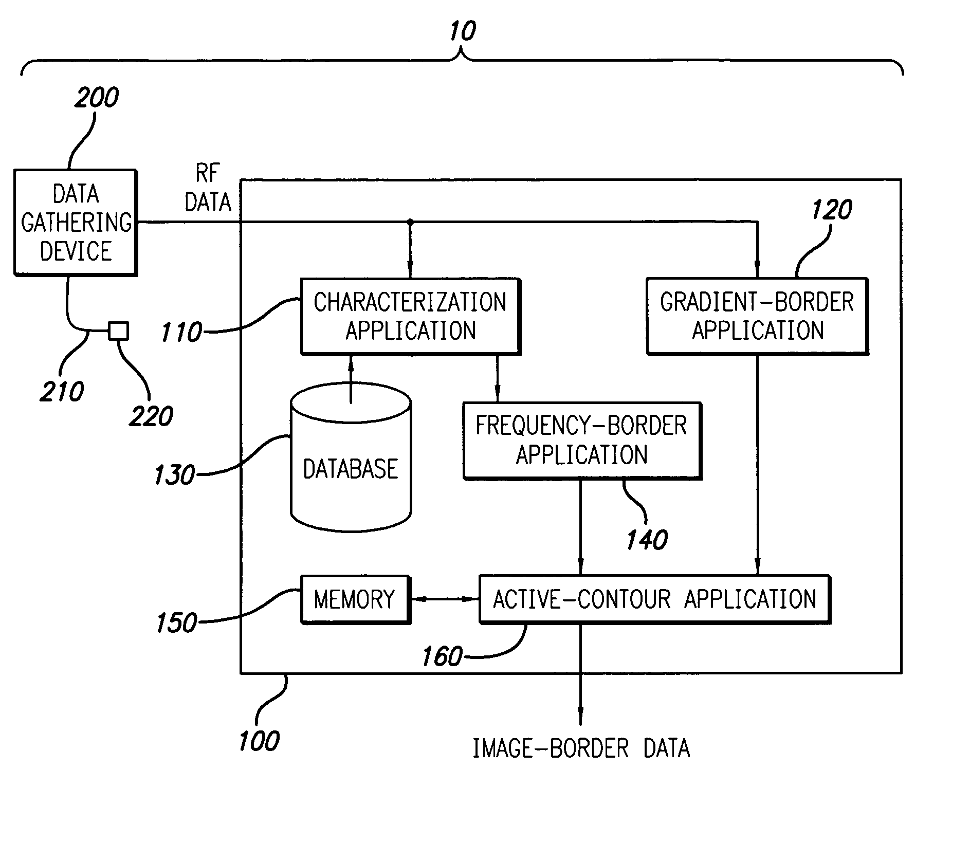
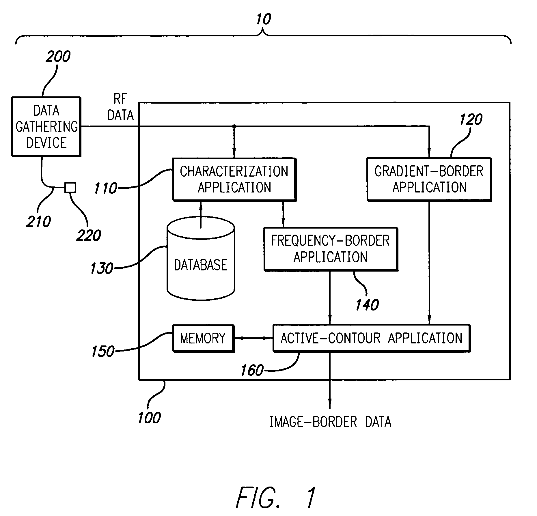
[0030]In the present invention, a plurality of tissue types (e.g., medial, adventitial, plaque, blood, etc.) and related parameters are stored in a database 130. Preferably, the information is stored so that each tissue type is linked to its corresponding parameters. By doing so, each tissue type can be identified (or defined) by the parameters that are linked thereto. It should be appreciated that the term parameter, as that term is used herein, includes, but is not limited to maximum power, minimum power, frequencies at maximum and / or minimum power, y intercepts (estimated or actual), slope, mid-band fit, integrated backscatter, tissue depth, and all parameters (either time or frequency based) generally known to (or discernable by) those skilled in the art. It should further be appreciated that the methods used to acquire the parameters or their relationship to the tissue types (e.g., using scientific theory, experimentation, computer simulation, etc.) are not a limitation of the ...

second embodiment

[0033]In the present invention, the characterization application 110 is further used to identify parameters from the RF data (which is typically in the time domain). Parameters associated with the RF data (or a portion thereof) can be used, for example, to spatially identify certain frequencies (or parameters related thereto). Thus, for example, if a vascular wall comprises multiple tissue layers, corresponding RF data can be used to identify the location of these tissues and the related frequency spectrum can be used to identify tissue types. The use of parameters to identify tissue types is discussed in detail in U.S. Pat. No. 6,200,268, which was issued on Mar. 13, 2001, and U.S. patent application Ser. No. 10 / 647,971, which was filed on Aug. 25, 2003, and are incorporated herein, in their entireties, by reference.

[0034]In either embodiment of the present invention, the RF data (or a transformation thereof) and the identified tissue types (including the association therebetween) ...


PUM


Abstract

A system and method is provided for using the frequency spectrum of a radio frequency (RF) signal backscattered from vascular tissue to identify at least one border (e.g., tissue interface, etc.) on a vascular image. Embodiments of the present invention operate in accordance with a data gathering device (e.g., an intra-vascular ultrasound (IVUS) device, etc.) electrically connected to a computing device and a transducer via a catheter. The transducer is used to gather radio frequency (RF) data backscattered from vascular tissue. The RF data is then provided to (or acquired by) the computing device via the data-gathering device. In one embodiment of the present invention, the computing device includes (i) at least one data storage device (e.g., database, memory, etc.) for storing a plurality of tissue types and parameters related thereto and (ii) at least one application (e.g., a characterization application, a gradient-border application, a frequency-border application and / or an active-contour application). The characterization application is used to convert (or transform) the RF data into the frequency domain and to identify a plurality of parameters associated therewith. The identified parameters are then compared to the parameters stored in the data storage device to identify the corresponding tissue type. This information (e.g., tissue type, corresponding RF data, etc.) is then used, either alone or together with other border-related information (e.g., gradient information, other-border information, etc.), to determine at least one border on a vascular image.

Description

CROSS-REFERENCE TO RELATED APPLICATIONS[0001]This application claims the benefit pursuant to 35 U.S.C. § 119(e) of U.S. Provisional Patent Application No. 60 / 550,620, which was filed Mar. 4, 2004, and is incorporated herein, in its entirety, by reference.BACKGROUND OF THE INVENTION[0002]1. Field of the Invention[0003]The present invention relates to vascular images, or more particularly, to a system and method of using the frequency spectrum of a radio frequency (RF) signal backscattered from vascular tissue to identify at least one border on a corresponding vascular image.[0004]2. Description of Related Art[0005]The present invention relates to medical imaging arts. It finds particular application to a system and method of identifying a border on a vascular image (e.g., intra-vascular ultrasound (IVUS) image, Virtual Histology™ (VH) image, etc.). It should be appreciated that while the present invention is described in terms of identifying a luminal and medial-adventitial border on...

Claims


Application Information

Patent Timeline
Patent Type & Authority Patents(United States)
IPC IPC(8): G06K9/00A61B8/08A61B8/12
CPCA61B5/02007A61B8/0858A61B8/12
Inventor KLINGENSMITH, JON D.NAIR, ANUJAKUBAN, BARRY D.VINCE, D. GEOFFREY
Owner THE CLEVELAND CLINIC FOUND
Why Eureka
Try Eureka