Radio-frequency receiver and integrated circuit for use in receiver
a radio frequency receiver and integrated circuit technology, applied in the field of radio frequency receivers, can solve problems such as image interruption, and achieve the effect of reducing image interference components
- Summary
- Abstract
- Description
- Claims
- Application Information
AI Technical Summary
Benefits of technology
Problems solved by technology
Method used
Image
Examples
exemplary embodiment 1
(Exemplary Embodiment 1)
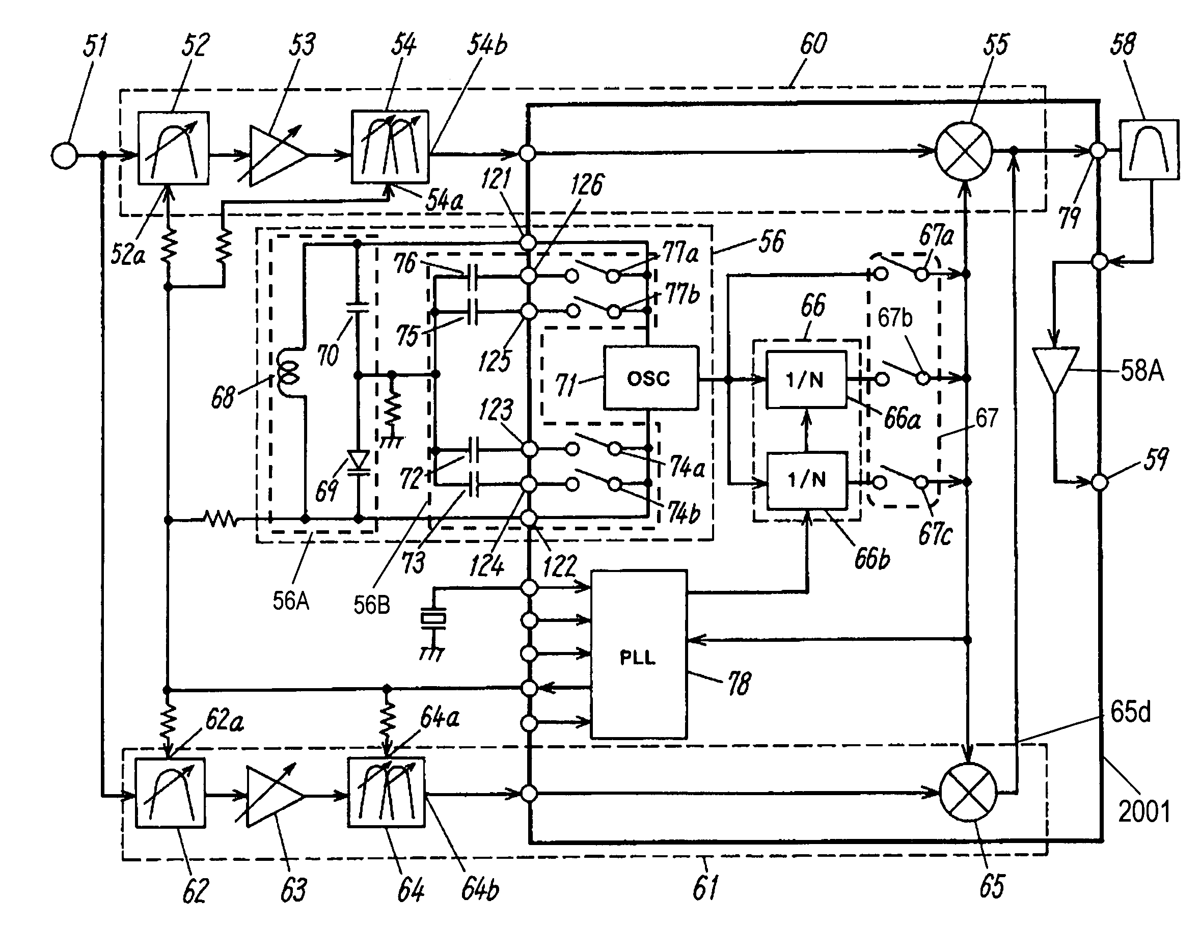
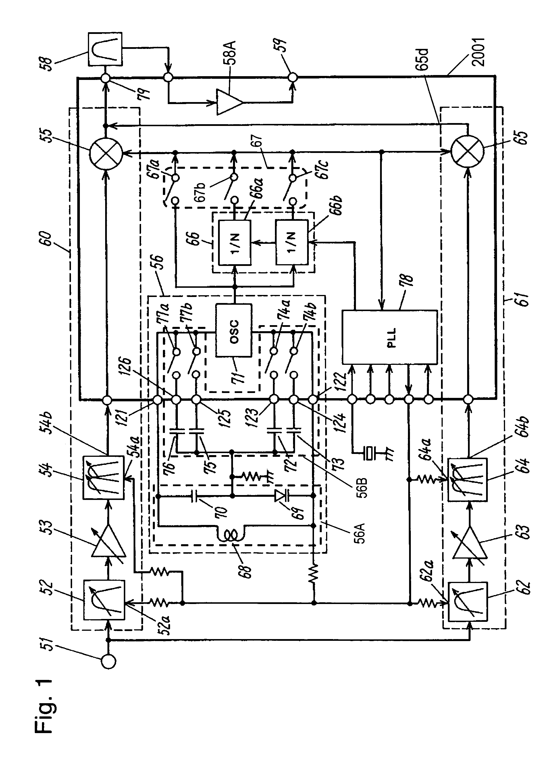
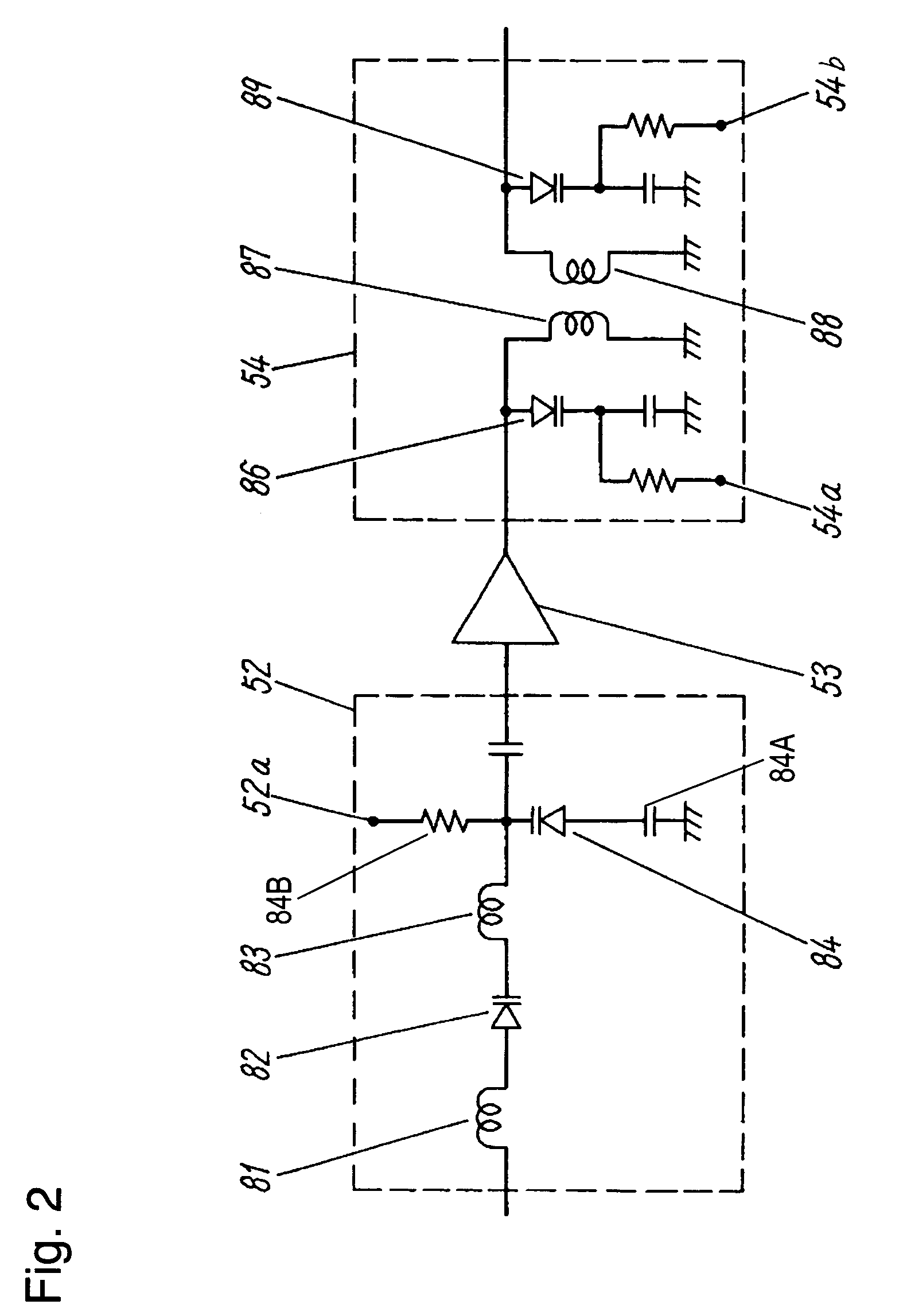
[0028]FIG. 1 is a block diagram of a radio-frequency (RF) receiver according to Exemplary Embodiment 1 of the present invention. An RF signal ranging from 55.25 MHz to 801.25 MHz is received at an input terminal 51. A single-tuned filter 52 is connected to the input terminal 51 and implemented by a signal variable capacitance diode and has a tuning frequency variable within an UHF band from 367.25 MHz to 801.25 MHz in response to a tuning voltage supplied to a frequency variable port 52a.
[0029]An RF amplifier 53 amplifies a signal output of the UHF band output from the single-tuned filter 52. The radio-frequency amplifier 53 has an output port connected to a double-tuned filter 54 which is composed by two variable capacitance diodes and has a tuning frequency variable in response to a tuning voltage supplied to a frequency variable port 54a.
[0030]A mixer 55 has one input port for receiving a signal output from the double-tuned filter 54 and has other input ...
exemplary embodiment 2
(Exemplary Embodiment 2)
[0096]FIG. 6 is a block diagram of a radio-frequency (RF) receiver according to Exemplary Embodiment 2 of the present invention. The same components as those of Embodiment 1 shown in FIG. 1 are denoted by the same reference numerals and will be explained in no more detail.
[0097]A local oscillator 356 generates a signal having a frequency ranging from 700 MHz to 1700 MHz, which is twice greater than that of the local oscillator 56 of Embodiment 1 shown in FIG. 1. The local oscillator 356 includes an inductor 368 and a variable capacitance diode 369 to generate the signal of the oscillation frequency ranging from 700 MHz to 1700 MHz. Upon capacitances of capacitors 372, 373, 375, and 376 being determined appropriately, characteristics of frequency changes against tuning voltages of the single-tuned filters 52 and 62 and the double-tuned filters 54 and 64 are made similar to each other, so that their passing frequency is differentiated by a range of an intermedi...
exemplary embodiment 3
(Exemplary Embodiment 3)
[0111]According to Exemplary Embodiment 3 of the present invention, a VHF signal receiver section 61 of a radio-frequency (RF) receiver of Embodiment 1 shown in FIG. 1 employs an image rejection mixer for receiving a VHF high band and employs a harmonic rejection mixer for receiving a VHF low band.
[0112]FIG. 8 is a block diagram of the RF receiver of Embodiment 3. The same components as those of Embodiment 1 shown in FIG. 1 are denoted by the same reference numerals and will be explained in no more detail. An RF signal having a frequency ranging from 55.25 MHz to 801.25 MHz is input to an input terminal 51 A UHF band receiver section 560 includes a single-tuned filter 52, an RF amplifier 53, a double-tuned filter 54, a mixer 55, and an intermediate frequency filter 58.
[0113]A VHF band receiver section 561 connected to the input terminal 51 receives signals in a VHF band ranging from 55.25 MHz to 361.25 MHz. The VHF band receiver section 561 includes a single-...
PUM
 Abstract
Description
Claims
Application Information
 - R&D
- Intellectual Property
- Life Sciences
- Materials
- Tech Scout
- Unparalleled Data Quality
- Higher Quality Content
- 60% Fewer Hallucinations
Browse by: Latest US Patents, China's latest patents, Technical Efficacy Thesaurus, Application Domain, Technology Topic, Popular Technical Reports.
© 2025 PatSnap. All rights reserved.Legal|Privacy policy|Modern Slavery Act Transparency Statement|Sitemap|About US| Contact US: help@patsnap.com


