Carabiner attachment bracket for a basket rescue stretcher

a basket rescue and bracket technology, applied in the field of basket rescue stretchers, can solve the problems of reducing the safety of use of the stretcher, affecting the safety of use, and the contact of the cable, so as to reduce the snagging or abrading of the lifting equipment, and the effect of balanced and stabl

Inactive Publication Date: 2007-05-15
TRAVERSE RESCUE
View PDF24 Cites 5 Cited by
  • Summary
  • Abstract
  • Description
  • Claims
  • Application Information

AI Technical Summary

Benefits of technology

[0010]The stretcher of the present invention has attachment brackets which are inwardly disposed into the stretcher basket and located near the fore and aft ends of the stretcher, located equidistant from a longitudinal axis of the stretcher. Brackets which extend externally of the stretcher may also be employed, and if so, advantageously they form a smoothly curved surface to avoid snagging. The brackets permit the stretcher to be raised or lowered adjacent to a vertical or inclined surface, such as the outside of a building or an escarpment, in a manner which is relatively balanced and stable and which reduces snagging or abrading of lifting equipment against the adjacent surface of the slope.
[0014]The mounting member is rigid and may be a bracket, or loop, or apertured plate which is mountable or mounted to the stretcher so that when a clip, carabiner, hook or the like is attached to the mounting member, twisting of the sling webbing is avoided.

Problems solved by technology

Thus, the difference in top rail and carabiner diameters prevents the carabiner from properly contacting the underside of the top rail of the basket stretcher as tension is applied.
In situations where a “shock load” is placed on the basket stretcher, such as if a loaded stretcher was dropped a short distance and then arrested by the carabiners and connecting tethers, opposite sides of the tubular top rail could be crushed slightly, thereby weakening the rail and perhaps rendering the stretcher unsafe for use.
Such movement of the connecting point between tether and stretcher in undesirable since it results in an imbalance of both stretcher and patient and could further endanger the patient.
Further, as tension is applied to the tether straps during suspension of the basket stretcher, the top rail of the basket stretcher prohibits the carabiner from rotating so as to lie in the plane of the tether straps or webbing were the webbing to remain flat, resulting in the carabiner being misaligned generally 90 degrees from such an orientation causing a helical twist in the straps or webbing.
Such an outwardly exposed portion may snag on surface irregularities on the adjacent surface of a building or an escarpment as the basket stretcher is raised or lowered resulting in tipping and jerking of the basket stretcher as it elevates or descends.
Further, such contact may result in rapid abrading and deterioration of the carabiner.

Method used


Image

  • Carabiner attachment bracket for a basket rescue stretcher
  • Carabiner attachment bracket for a basket rescue stretcher
  • Carabiner attachment bracket for a basket rescue stretcher

Examples


Embodiment Construction

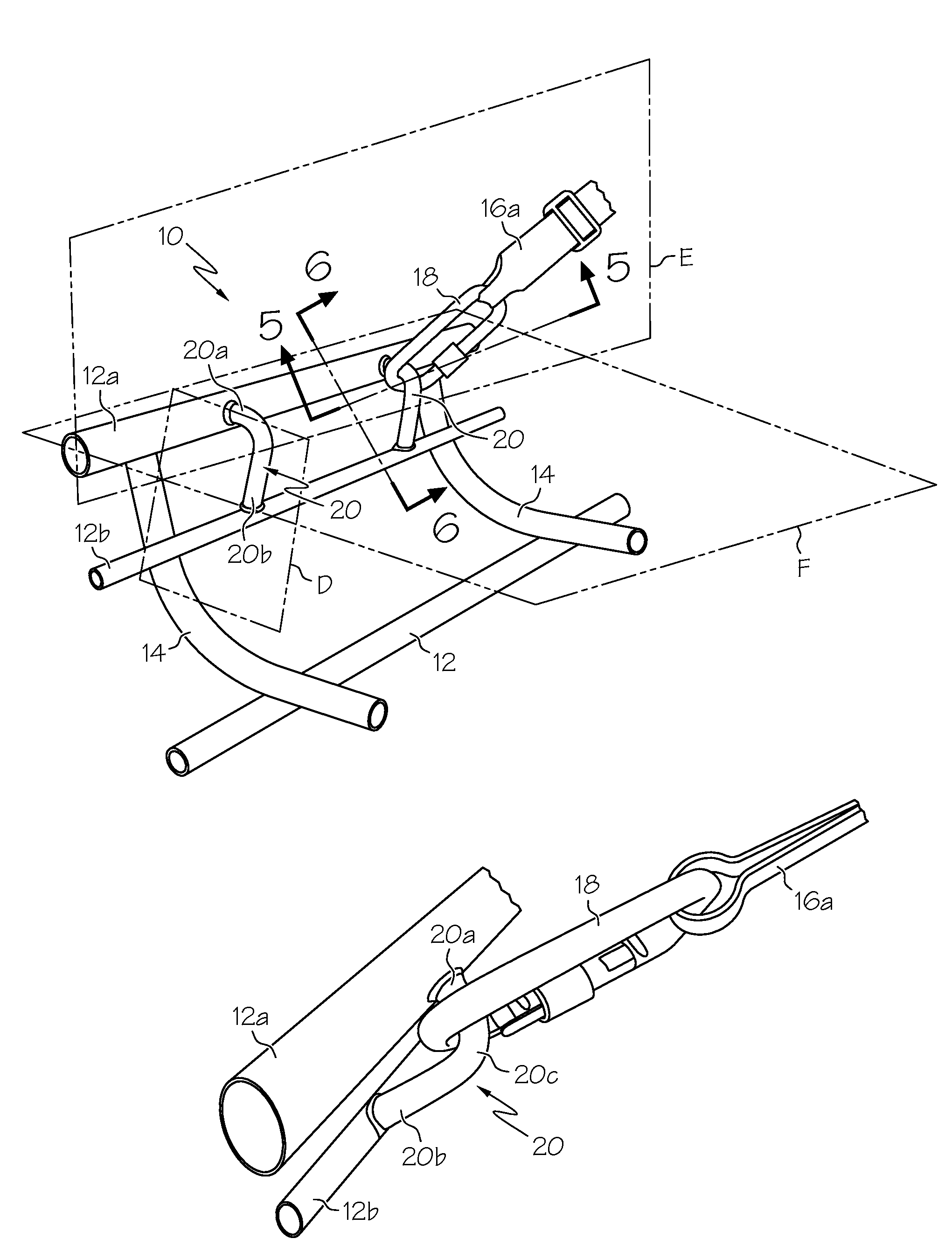
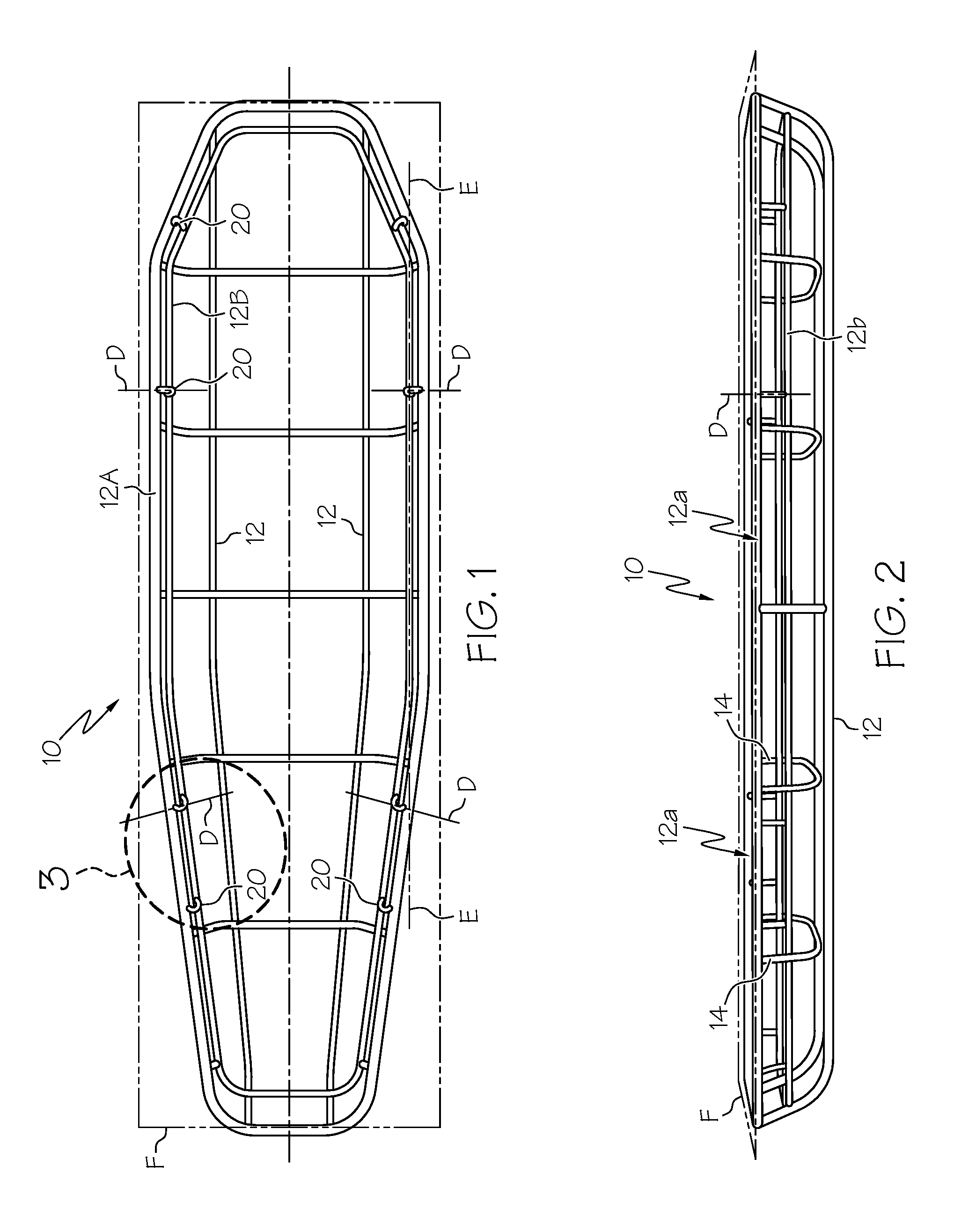
[0032]With reference to the drawing figures wherein similar characters of reference denote corresponding parts in each view, as seen in FIGS. 1 and 2 basket rescue stretcher 10 includes longitudinal and lateral members such as stringers 12 and ribs 14. Stringers 12 and ribs 14 are welded together to form a rigid elongate low-sided basket. Continuous peripheral top rail 12a surrounds the basket opening. One or more intermediate rails 12b are spaced from and parallel to top rail 12a.

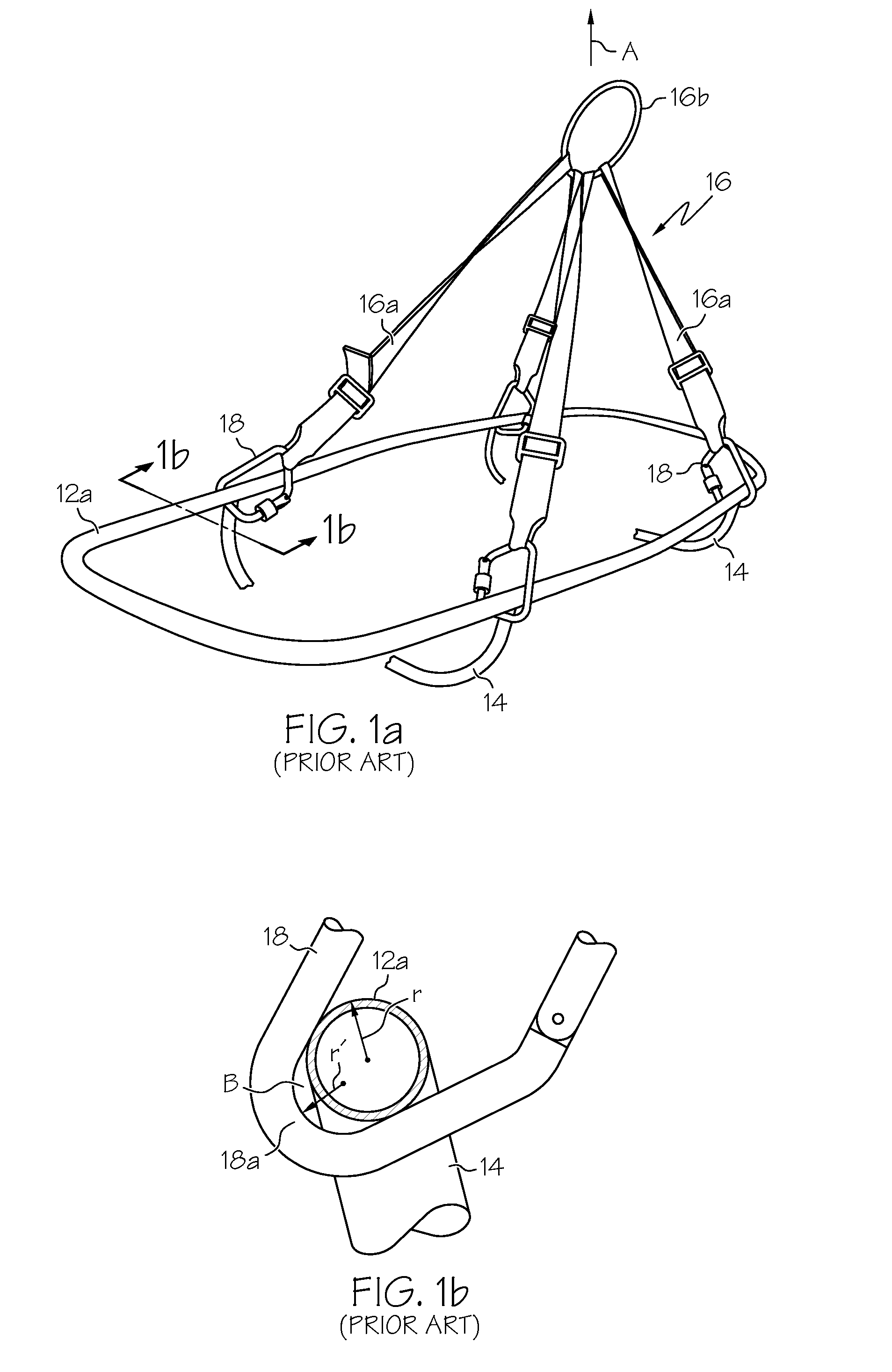
[0033]In the prior art as seen in FIGS. 1a and 1b, a conventional lifting tether 16 is attached to the top rail 12a of basket stretcher 10 by conventional screwgate carabiners 18. When lifting tether 16 is tensioned in direction A, carabiner 18 will have a tendency to slide longitudinally along top rail 12a unless carabiner 18 is positioned such that any sliding movement that occurs will be immediately arrested by contact with a lateral frame component 14, such as a rib, which intersects and is secured to...


PUM


Abstract

A pair of carabiner mounting members are rigidly mounted or mountable to each top rail of a basket rescue stretcher. The carabiner mounting members are mounted or mountable spaced longitudinally apart along the each top rail. Carabiner mounting member extend at least into the stretcher cavity and define a carabiner receiving opening which lies in a first plane which is perpendicular to a vertical second plane containing the corresponding top rail to which the carabiner mounting member is mounted or mountable and which is inclined relative to a horizontal third plane which contains the pair of top rails on opposite sides of the stretcher so that at least the carabiner mounting members which extend into the stretcher cavity are substantially co-planar with their corresponding tether straps when the stretcher is lifted by the straps.

Description

CROSS REFERENCE TO RELATED APPLICATION[0001]This application is a Continuation-in-Part of Ser. No. 10 / 797,113, now U.S. Pat. No. 6,859,963, filed Mar. 11, 2004 which is a Continuation of Ser. No. 10 / 361,580, now U.S. Pat. No. 6,725,480 filed Feb. 11, 2003 which claims priority from U.S. Provisional Patent Application No. 60 / 355,787 filed Feb. 12, 2002, entitled Attachment for a Basket Rescue Stretcher.FIELD OF THE INVENTION[0002]This invention relates to an improvement in basket rescue stretchers and in particular to a carabiner attachment for stretchers such as stokes litters.BACKGROUND OF THE INVENTION[0003]A basket rescue stretcher of the type utilized by emergency personnel is well known. It generally comprises a sturdy, light-weight, open frame manufactured from stainless steel tubing or like material, comprising both longitudinal and lateral components which are secured by welding or the like, into an integral unit. Common to most rescue stretchers of this type is a sturdy per...

Claims


Application Information

Patent Timeline
Patent Type & Authority Patents(United States)
IPC IPC(8): A47B1/00A61G1/00A61G1/048A61G1/04
CPCA61G1/04
Inventor SAWATZKY, RANDAL G.
Owner TRAVERSE RESCUE
Why Eureka
Try Eureka