Guide actuator with high radial direction load capacity

Active Publication Date: 2007-05-15
HIWIN TECH
View PDF6 Cites 9 Cited by
  • Summary
  • Abstract
  • Description
  • Claims
  • Application Information

AI Technical Summary

Benefits of technology

[0007]The purpose of the present invention is to resolve the disadvantages of the commonly known technology described above such as low stiffness, high difficulty of assembly and lack in bearing heavier downward load and sufficient moment of inertia for the mechanism so as to provide a new type guide actuator.
[0008]In order to improve the disadvantages of the commonly known technology, the present invention utilizes the U-shape guide structure with redesigning. As the moment of inertia for a U shaped lamina structure with respect to a defined axis is greater than that of a rectangular lamina with siminar length of two edges to that of the U shaped structure, so that the moment of inertia of the structure will be improved. The direction of bearing force of the guide structure is changed to make the linear guide actuator have better stiffness and precision, such that the U shape guide structure has not only a sufficient bending moment but an anti-distortion stress and a radial direction load capability.
[0009]According to the present invention, the first pair of grooves are set at the center of the bottom of the U-shape guide structure, and a table is set between the two inner walls of both sides of the U-shape structure, and two grooves corresponding to the grooves on the U-shape structure are set at the bottom of the table with setting rollers therein to make the table enable to slide with respect to the U-shape guide structure with low friction according to rolling motion of the rollers. The intensity of the present invention is good because the bottom of the U-shape guide structure is directly locked on the base of the mechanical structure. Besides, the table and the grooves thereon, rollers, U-shape guide structure and the grooves thereon are arranged in alignment from the upside to the underside such that the direction of bearing force is identical to make the guide actuator with high radial direction load capability of the present invention have good ability of bearing load.

Problems solved by technology

The assistant frame is usually made of cast iron, but it is more difficult in manufacturing process and more expensive in cost.
However, aluminum has low stiffness such that linearity and parallelism are relatively more unstable.
Unfortunately, most guide actuators are set in this way, including the single axis type and two axes type, X-Y actuator.
As long as the mechanism on the table is too heavy or the table bears too much load downward, the precision of the actuator would be affected obviously.
Moreover, the actuator may bears too heavy load to be destroyed.
Since the rail provided in this case is designed to configure into a narrow, elongated small cross section element whose cross sectional moment of inertia is very small, the rail is apt to be distorted and flexed causing inconvenient to assemble.
Moreover, the planarity of the base entraining the mechanism greatly affects the parallelism of table movement.
As a result production efficiency of the machine will be greatly lowered by spending too much labor force for calendering and caliberating the base.

Method used


Image

  • Guide actuator with high radial direction load capacity
  • Guide actuator with high radial direction load capacity
  • Guide actuator with high radial direction load capacity

Examples


Embodiment Construction

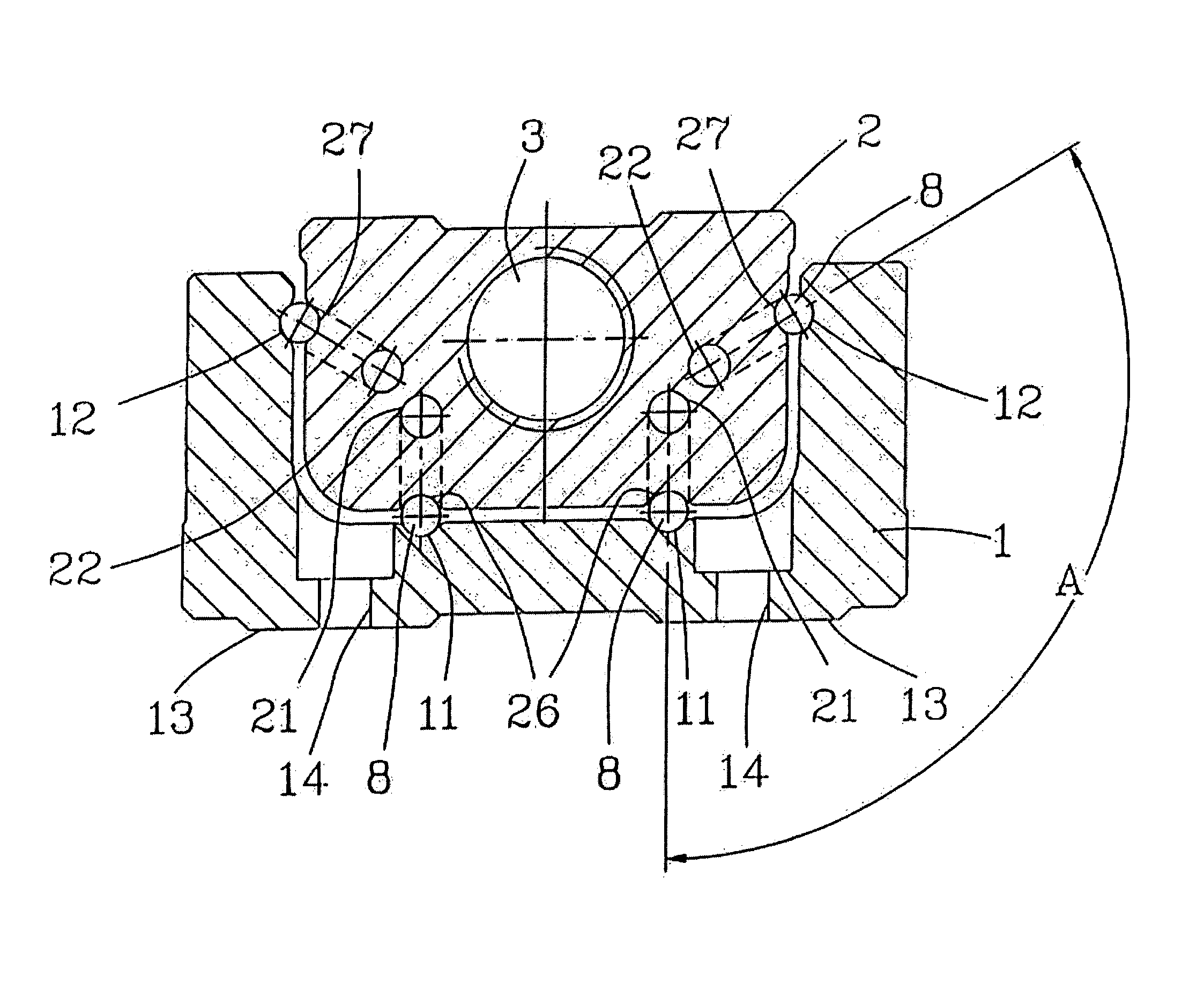
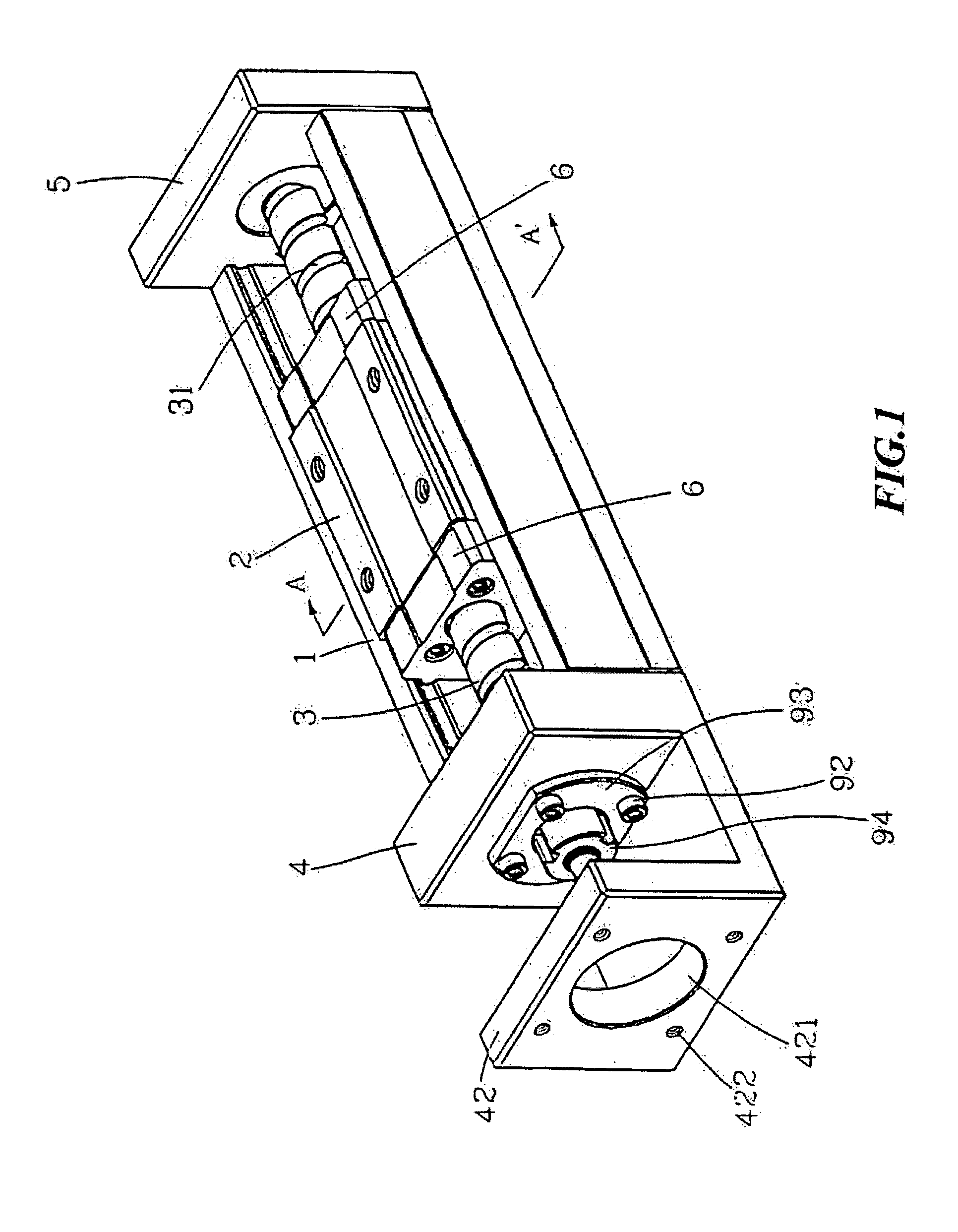
[0018]FIG. 1 is the schematic diagram of the guide actuator with high radial load capability. In the figure, the actuator uses a ball screw to transmit. Besides, a motor (not shown in figures) is locked on the motor seat (42) of the bearing seat (4), and screw holes (422) are used to be passed through by screws to fasten the motor. A hole (421) is used to be passed through by the output end portion of the motor. The screw (3) has threads (31), and both ends thereof are limited by the bearing seat (4) and the bearing seat (5). The left end of the screw (3) is positioned by screws (92), a bearing ring (93) and a locking nut (94), and can be connected to the motor fastened on the motor seat (42) with a coupling (not shown in figures). The rotation of the motor can drive the screw (3) to rotate such that the table (2) setting outside the screw (3) can move leftward or rightward due to that the internal threads of the table (2) is engaged with the threads (31) of the screw (3).
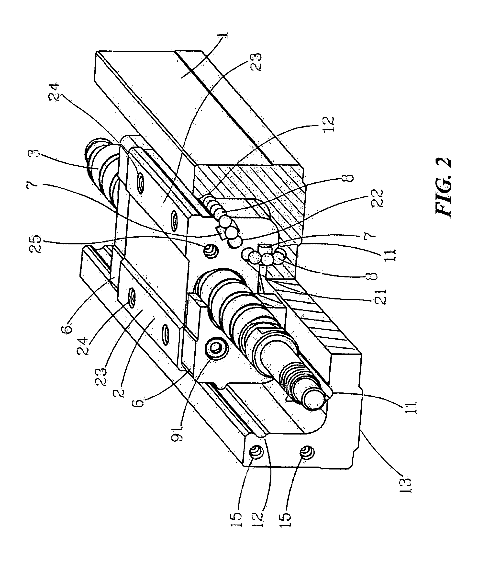
[0019]FIG....


PUM


Abstract

The present invention relates to a new guide actuator with high radial direction load capability, which has the purpose of providing a directional force bearing way to common loading method to make the actuator can bear load and transmit with higher accuracy. On design, the present invention has grooves bearing load at the center of the bottom of the U-shape guide structure, and a table is set between two inner side walls of the U-shape guide structure, grooves corresponding to the grooves of the U-shape guide structure being set at the bottom of the table, rollers being set between grooves and grooves to make the table and the U-shape guide structure slide respect to each other with very low friction due to rolling motion of the rollers with high radial load capability.

Description

CROSS-REFERENCES TO RELATED APPLICATIONSThe present invention is a Continuation-in-part (CIP) application of a pending non-provisional patent application with application Ser. No. 10 / 086,433 filed Mar. 4, 2002 now abandoned.BACKGROUND OF THE INVENTION[0001]1. Field of the Invention[0002]The present invention relates to a guide actuator fit to be applied on machining tools, robotics, electrical equipments and automation industry, and so on, especially to a new one having U-shape guide structure and enabling to bear higher radial load.[0003]2. Description of the Prior Art[0004]Commonly known linear guide actuators are mainly composed of a pair of parallel linear slide rails fastened on an assistant frame, a movable table locked on a table of the linear slide rail, and a screw or a belt used as an actuating structure to drive the table to move back and forth (as U.S. Pat. No. 5,598,043). The assistant frame is usually made of cast iron, but it is more difficult in manufacturing process...

Claims


Application Information

Patent Timeline
IPC IPC(8): F16H27/02F16C29/06F16H25/20
CPCF16C29/063F16H25/20F16H2025/2034Y10T74/19749Y10T74/18648Y10T74/19753F16H2025/204
Inventor KUO, CHANG-HSINCHEN, TUNG-HSIN
Owner HIWIN TECH
Why Eureka
Try Eureka